Datamax-O'Neil M-Class Mark II RFID Ready Option User Manual
Page 9
7
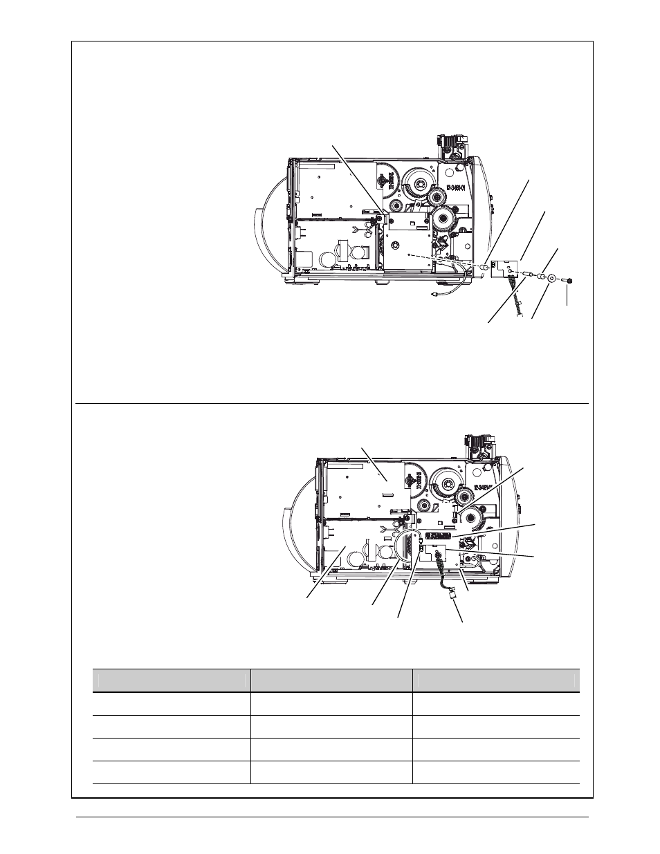
HF Option:
G) Place the Washer (Item
11) and then the Long
Spacer (Item 10) onto the
Screw (Item 8). Place a
Short Spacer (Item 9)
over the Long Spacer and
Screw. Insert the Long
Spacer and Screw
through the HF Module
(Item 14). Place a Short
Spacer (Item 9) over the
Long Spacer and Screw
then secure the assembled
parts to the Mounting
Plate, as shown.
Short
Spacer
Mounting
Plate
Screw
Short
Spacer
Long
Spacer
HF
Module
Washer
H) Affix the FCC Label (Item
13) to the Mounting
Plate. Route the Antenna
Cable behind the
Mounting Plate and then
connect the cables
according to the table
below:
Regulator
CCA
Mounting
Plate
Power
Supply CCA
J1
Main Logic
CCA
Antenna
Port
J2
J3
I/O
J12
J7
Antenna
Cable
HF
Module
FCC Label
Cable
From
To
Antenna Cable
Antenna
Antenna Port – HF Module
Power Cable (Item 4)
J7 – Power Supply CCA
J1 - Regulator CCA
Comm Cable (Item 5)
J12 – Main Logic CCA
J2 – Regulator CCA
I/O
HF Module
J3 – Regulator CCA
- MF8I 270 User Guide (20 pages)
- MF8I Installation Guide (18 pages)
- MF8I Truck Mount Cable (2 pages)
- MF8I Locking Mounting Bracket (2 pages)
- MF8I Economy Mounting Bracket (2 pages)
- MF8I AN-15 (Line Printer and Easy Print Modes) (7 pages)
- MF8I AN-16 (Single Byte Character Set Font File Format) (8 pages)
- MF8I Quick Reference Programming Guide (72 pages)
- MF8I Configuration Program Installation (1 page)
- MF8I Bluetooth Management Component for Wavelink Avalanche (10 pages)
- A-Class Mark II Operator’s Manual (160 pages)
- A-Class Mark II Installation (2 pages)
- A-Class Mark II DMXrfNetIII (16 pages)
- A-Class Mark II DMXrfNetII (16 pages)
- A-Class Mark II RFID Quick Start Guide (6 pages)
- A-Class Mark II Programmer’s Manual (334 pages)
- ANDES 3 User Guide (32 pages)
- ANDES 3 Quick Start Guide (2 pages)
- ANDES Series Programmer’s Manual (67 pages)
- APEX 2 User Guide (28 pages)
- APEX 2 Quick Start Guide (2 pages)
- APEX 3 User Guide (27 pages)
- APEX 3 Quick Start Guide (2 pages)
- APEX 4 User Guide (30 pages)
- APEX 4 Quick Start Guide (2 pages)
- E-Class Mark III Operator’s Manual (90 pages)
- E-Class Mark III 4xxxxxxx Operator’s Manual (58 pages)
- E-Class Mark III 3xxxxxxx Operator’s Manual (58 pages)
- E-Class Mark III Paper Menu (7 pages)
- E-Class Mark III DPL Programmer’s Manual (296 pages)
- E-Class Mark III Printhead Bracket and Screw Upgrade (11 pages)
- H-Class Operator’s Manual (180 pages)
- Static brush (2 pages)
- H-Class Media Retainer (1 page)
- H-Class Thermal Transfer Option (12 pages)
- H-Class RFID Option (8 pages)
- H-Class Powered Internal Rewind Option (10 pages)
- H-Class Internal Rewind Option (6 pages)
- H-Class Present Sensor Option (8 pages)
- H-Class Peel & Present Option (8 pages)
- H-Class Linear Scanner Option (26 pages)
- H-Class HD Peel & Present Option (10 pages)
- H-Class HD Cutter Option (12 pages)
- H-Class GPIO Option (14 pages)
- H-Class Cutter Option (10 pages)