Transmitter receiver – BEI Sensors SwiftComm® Real-Time Wireless Encoder Interface User Manual
Page 5
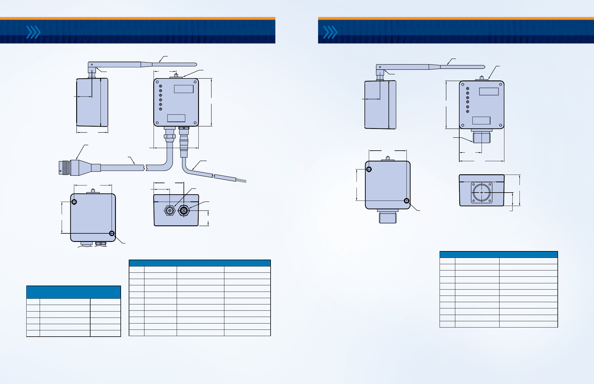
Transmitter
Receiver
PWR
A
B
Z
LINK
STATUS
Encoder Output
Antenna
Receiver
50mW
2.4GHz
ENCODER OUT
3.13
2.94
CONNECTOR:
MS3102R18-1P
1.48
TYP
1.00
CONNECTOR:
RP-TNC
2.465
2.063
SWIVEL JOINT
ANTENNA 8.0" OVERALL LENGTH
BOTTOM
VIEW
2X 1/4-20UNC
X 1.5" DP. MAX.
MOUNTING HOLES
0.88
2.05
NOTE:
ALLOW 5.0" FROM
EDGE OF MODULE FOR
MS MATING CONN.
AND CABLE RADIUS
Encoder Input
LINK
STATUS
Transmitter
50mW
2.4GHz
A
B
Z
Antenna
PWR
Pwr Input
1.00
CONNECTOR:
MDC-5MR-PG9
1.00
3.13
2.94
1.48
POWER IN CABLE:
MENCOM MDC-5FP-2M
2 METERS LG.
P/N: 924-31320-K52M
CONNECTOR:
RP-TNC
1.05
1.97
SWIVEL JOINT
ANTENNA 8.0" OVERALL LENGTH
NOTE:
ALLOW 3.0" FROM
EDGE OF MODULE
FOR CABLE RADIUS
2X 1/4-20UNC
X 1.5" DP. MAX.
MOUNTING HOLES
2.063
2.465
BOTTOM
VIEW
CABLE: 10.0'
CONNECTOR:
MS3106F18-1S
ENCODER IN POWER IN
PG9 CABLE GLAND
2.05
The SwiftComm Transmitter Module has two connector
plugs: a 5-pin connector for power input, B.I.T output and
chassis ground; and a 3-meter cable with a 10-pin MS
connector attached to the end.
The SwiftComm Receiver Module has an MS connector
that provides the same output signals as a standard
BEI encoder.
Input power can be from 5 to 28 VDC. Output signals
(specified at time of ordering) can be 5 VDC or V in.
The B.I.T output signals indicate the RF Link Status.
Case ground is connected to earth ground. Circuit
ground is electrically isolated from the case ground.
Both of these grounds are typically connected together
at the power supply.
8 |
BEI Sensors
|
swiftcomm installation manual and user Guide
swiftcomm installation manual and user Guide
|
BEI Sensors
| 9
Transmitter
Receiver
PWR
A
B
Z
LINK
STATUS
Encoder Output
Antenna
Receiver
50mW
2.4GHz
ENCODER OUT
3.13
2.94
CONNECTOR:
MS3102R18-1P
1.48
TYP
1.00
CONNECTOR:
RP-TNC
2.465
2.063
SWIVEL JOINT
ANTENNA 8.0" OVERALL LENGTH
BOTTOM
VIEW
2X 1/4-20UNC
X 1.5" DP. MAX.
MOUNTING HOLES
0.88
2.05
NOTE:
ALLOW 5.0" FROM
EDGE OF MODULE FOR
MS MATING CONN.
AND CABLE RADIUS
Encoder Input
LINK
STATUS
Transmitter
50mW
2.4GHz
A
B
Z
Antenna
PWR
Pwr Input
1.00
CONNECTOR:
MDC-5MR-PG9
1.00
3.13
2.94
1.48
POWER IN CABLE:
MENCOM MDC-5FP-2M
2 METERS LG.
P/N: 924-31320-K52M
CONNECTOR:
RP-TNC
1.05
1.97
SWIVEL JOINT
ANTENNA 8.0" OVERALL LENGTH
NOTE:
ALLOW 3.0" FROM
EDGE OF MODULE
FOR CABLE RADIUS
2X 1/4-20UNC
X 1.5" DP. MAX.
MOUNTING HOLES
2.063
2.465
BOTTOM
VIEW
CABLE: 10.0'
CONNECTOR:
MS3106F18-1S
ENCODER IN POWER IN
PG9 CABLE GLAND
2.05
sWiftcomm transmitter module
sWiftcomm receiver module
*If transmission is interrupted for longer than 0.13 seconds the
status of this pin will change from LO to HI. B.I.T. is HI at +V level.
*If transmission is interrupted for longer than 0.13 seconds the status of this pin will
change from LO to HI. B.I.T. is HI at +V level.
Transmitter: Pwr Input & BIT Output
(5 Pin Connector)
Pin
Function
Color
1
+V (Supply Voltage)
BRN
2
B.I.T Output*
WHT
3
0V (Circuit Common)
BLU
4
——
BLK
5
Case Ground
GRY
Transmitter: Encoder Input (MS3106F18-1S or 10 ft pigtail)
Pin
Color (Pigtail)
Incremental Function
SSI Function
A
Yellow
A
DATA
B
Blue
B
CLOCK
C
Orange
Z
——
D
——
+V (Supply to Encoder)
+V
E
Black
——
——
F
——
0V (Supply to Encoder)
0V (Supply to Encoder)
G
Wh/Yellow
Case Gnd
——
H
Wh/Blue
A/
DATA
I
Wh/Orange
B/
CLOCK
J
Z/
——
Receiver Pinouts: Encoder Output (MS3102R18-1P)
Pin
Incremental Function
SSI Function
A
A
DATA
B
B
CLOCK
C
Z
——
D
+V (Supply Voltage)
+V
E
B.I.T Output*
B.I.T Output*
F
0V (Circuit Common)
0V (Circuit Common)
G
Case Gnd
——
H
A/
DATA
I
B/
CLOCK
J
Z/
——