Intrinsic safety barrier, Specifications, General wiring diagram – BEI Sensors Intrinsic Safety Barrier User Manual
Page 2: Power supply / output type, Barrier parameters, Input to barrier from encoder
7230 Hollister Avenue | Goleta, CA | 93117
Tel: 805.968.0782 / 800.960.2726
www.beisensors.com
Rev 2-20-14
Page 2/2
Intrinsic Safety Barrier
Specification No.: 02125-004
These commodities, technology or software if exported from the United States must be in accordance
with the Bureau of Industry, and Security, Export Administration regulations. Diversion contrary to U.S.
law is prohibited.
Specifications
POWER SUPPLY / OUTPUT TYPE
Part Number
Barrier Supply: Vs ±5%
Output logic to Non-hazardous Area Apparatus
60004-002
12-28 VDC
Vout = 5V
Line Driver
up to 100 mA source/sink
(TTL & RS422 compatible)
60004-003
Vout = Vin
Line Driver
up to 100 mA source/sink
60004-004
Open
Collector
NPN
up to 80 mA sink
60004-005
Vout = 5V
Line Driver
up to 100 mA source/sink
Open wire detect option
60004-006
Vout = Vin
Line Driver
up to 100 mA source/sink
Open wire detect option
Caution: Operation above or below barrier supply voltage (Vs) range noted will cause permanent damage to barrier
!
BARRIER PARAMETERS
Class I, Gp D
Class II, Gps E,F,G
Group IIA
Class I, Gps C,D
Class II, Gps E,F,G
Group IIB
Class I, Gps A,B,C,D
Class II, Gps E,F,G
Group IIC
Barrier Output
(Po)
Voc (Uo)
Isc (Io)
Ca (Co)
La (Lo)
L/R Ratio
Ca (Co)
La (Lo)
L/R Ratio
Ca (Co)
La (Lo)
L/R Ratio
870 mW
9.48 VDC
367 mA
255 uF
2.1 mH
327 uH/Ω
27 uF
1.05 mH
160 uH/Ω
3.7 uF
0.26 mH
40.8 uH/Ω
INPUT TO BARRIER FROM ENCODER
Signals
A, B, Z, A/, B/, Z/ differential or A,B,Z single-ended
Input Signal Impedance
500 Ω nominal (A to A/, B to B/, Z to Z/)
Input Signal level
4 VDC minimum, 6 VDC maximum
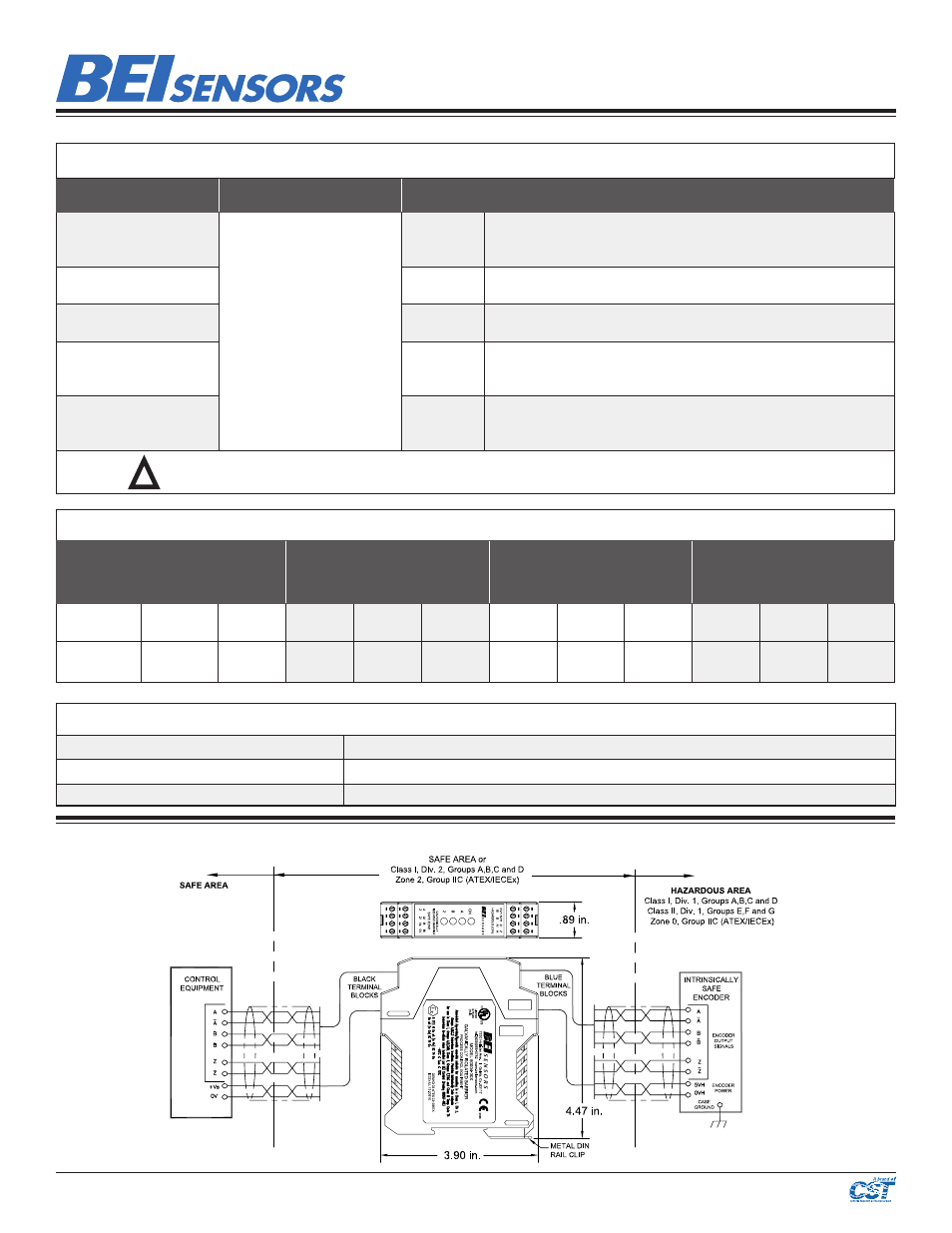
General Wiring Diagram
(See BEI Sensors drawing 08067-003 for important details)