AAON LC-054 User Manual
Page 42
42
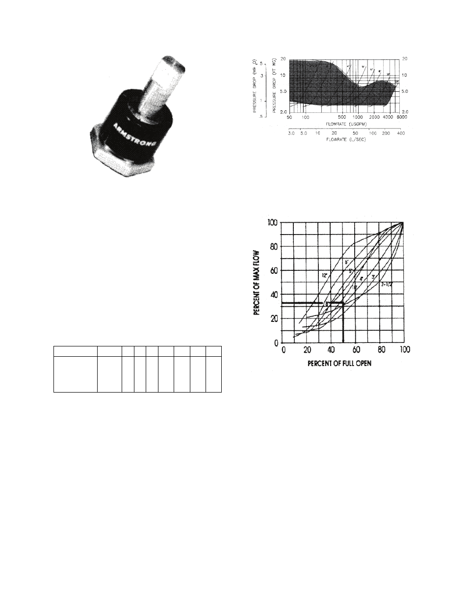
The quarter turn graduations on the sleeve,
with the scribed line on the stem provide an
approximate flow measurement.
Note: The valve is shipped in closed
position. The indicator on the plastic
sleeve is aligned with the vertical scribed
line on the stem.
Step 2. Record the size of the valve and
stem position using the flow indicator scale.
Calculate the percentage of valve opening
based on the number of rings at the fully
open position.
Valve Size 2-1/2 3 4 5 6
8 10 12
Number
of Rings
(valve fully
open)
5
5 6 9 10 12 18 28
Step 3. Measure and record the differential
pressure across the valve in the throttled
position.
Step 4. Locate percentage of valve opening
on the flow characteristic curve. For the
given valve, record the percentage of
maximum flow rate.
Step 5. Locate the differential pressure
determined for the valve in the throttled
position on the Flo-Trex Performance
Curve. Determine the flow rate for the
given valve size at this differential pressure.
Step 6. Calculate the flow rate of the valve
in the throttled position by multiplying the
flow rate (Step 5) by the percentage of
maximum flow rate (Step 4).
Example:
Valve size: 4 in.
Differential pressure is 5.4 ft
Number of open rings is 3.
From the table, the number of rings for the 4
in valve fully open is 6. Divide open rings
by total, 3/6 = 50% throttled
From the Flo-Trex performance curve, a 4
in. valve with 5.4 ft of pressure drop
represents a flow of 400 Usgpm