Appendix - water piping component information, Water pressure relief valve, Automatic air vent valves – AAON LC-054 User Manual
Page 27
27
Appendix - Water Piping Component Information
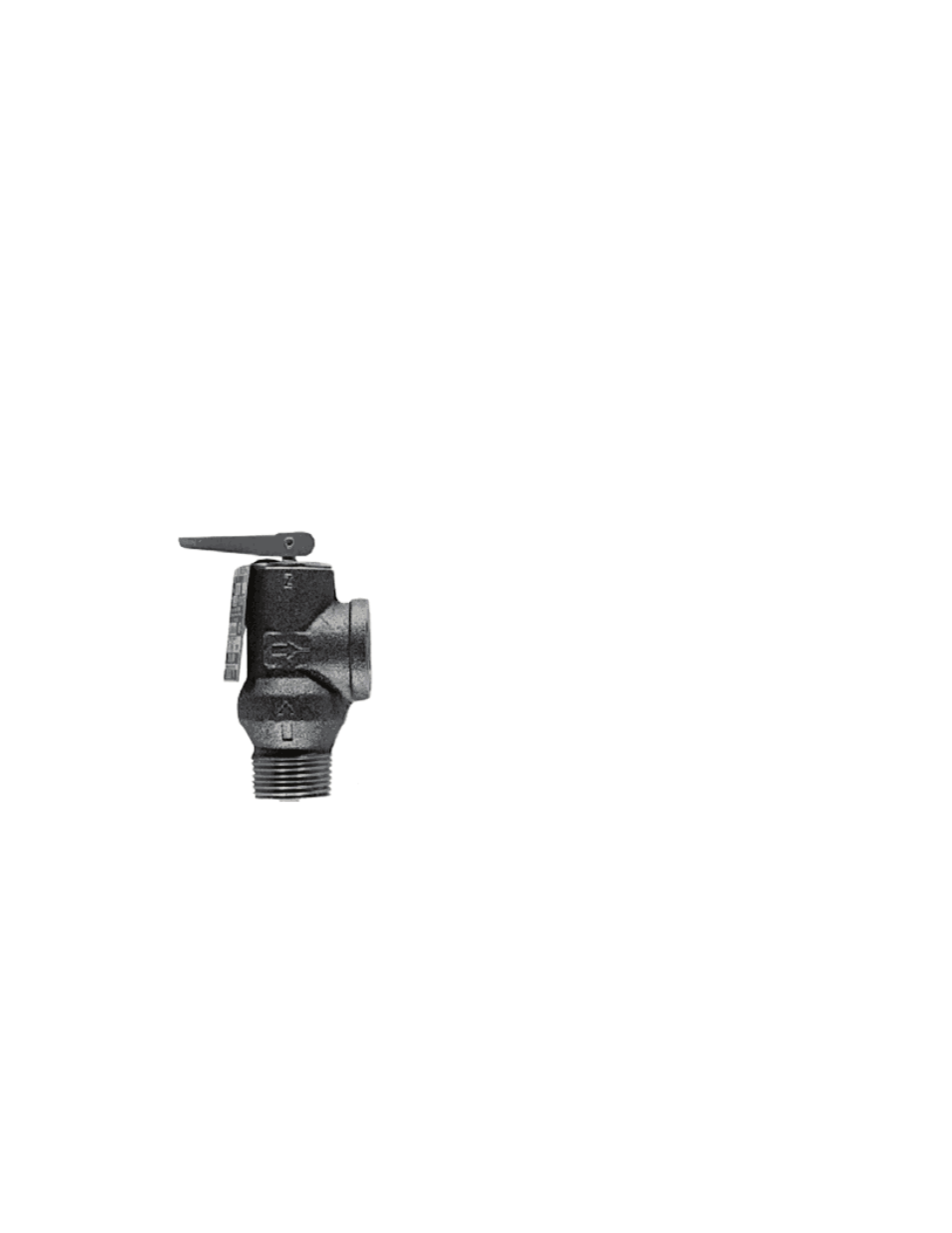
Water Pressure Relief Valve
Overview
ASME Rated, Design Certified and Listed
by C.S.A
.
Used for protection against excessive
pressure on domestic storage tanks or tank-
less water heaters, the pressure relief valve
has no temperature relieving element.
Standard setting is 125 psi Size 3⁄4” x 3⁄4”
(20mm x 20mm). ASME construction and is
tested, listed and certified by the National
Board of Boiler and Pressure Vessel
Inspectors.
ANSI Z21.22 “Relief Valves for Hot Water
Supply Systems.”
DESIGN CERTIFIED and listed by C.S.A.
Automatic Air Vent Valves
Automatic Air Vent Valves provide air
venting for hot or cold water distribution
systems. These vents purge air that may be
in the water system.
The vent valve utilizes an internal baffle
system. The baffles slow water so that
entrapped air can separate. Once the air is
separated, the air migrates to the top of the
scoop chamber. The air is vented through
the factory installed vent.
Overview
Air scoops are constructed of one piece cast
iron. Baffles are engineered to separate air
from water. All air scoops come with 1/8”
vent connection. An additional stainless
steel expansion tank connection is available
on the 1-1/2” to 4” air scoops. Air scoops
never require servicing. The high point vent
should be turned clockwise one to two
rotations to allow proper air venting. It is
not recommended to remove the cap as dirt
and debris may enter the water system.
Air scoops are suitable for use with water or
water/glycol systems.
Operating Range
Maximum operating pressure:
125 psi (862 kPa)
Maximum operating temperature:
300ºF (135ºC)
Recommended Flow Rate:
4 ft. / sec.
Maximum Flow Rate:
8 ft. / sec.