Flo-trex combination valve – AAON LC-054 User Manual
Page 40
40
Replace the permanent strainer into the
fitting body, once the temporary strainer is
removed.
Replace the cover into the body. Ensuring
that the strainer is properly seated, tighten
the cover bolts diagonally, evenly and
firmly.
Flo-Trex Combination Valve
Introduction
The Flo-Trex combination valves are
designed for installation on the discharge
side of centrifugal pumps, and incorporate
three functions in one valve:
1. Drip-tight shut-off valve
2. Spring closure design, Non-slam check
valve
3. Flow throttling valve
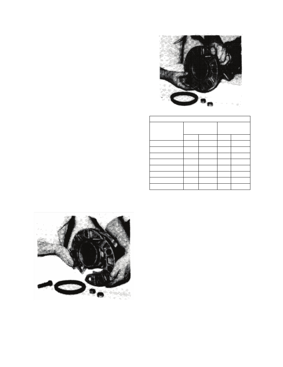
Armgrip Flange Adapter installation
1. Position the two halves of the Armgrip
flange adapter on the valve body ensuring
that the lugs on each half of the flange
adapters are located between the anti-
rotation lugs on the valve body (as shown).
Insert two bolts of specified size (Table A1)
to secure the halves of the flange adapter to
the valve body (as shown).
Armgrip Flange Adapter Details
Valve Size
125 psi/150 psi 250 psi/300 psi
Ductile Iron Bolt Ductile Iron Bolt
No.
Size
No.
Size
2-1/2
4
5/8
8
3/4
3
4
5/8
8
3/4
4
8
5/8
8
3/4
5
8
3/4
8
3/4
6
8
3/4
12
3/4
8
8
3/4
12
7/8
10
12
7/8
16
1
12
12
7/8
16
1-1/8
The gasket cavity should face out to the
adjoining flange.
2. Lubricate the inner and outer diameter of
the gasket with the lubricant provided or a
similar non-petroleum based water soluble
grease.
3. Press the gasket firmly into the flange
cavity ensuring that the sealing lip is pointed
outward. When in place, the gasket should
not extend beyond the end of the pipe (as
shown).