Primary pumping package, Glycol, Compression/expansion tank – AAON LC-054 User Manual
Page 14: Pressure relief valve, Manual and automatic air vent
14
Primary Pumping Package
Primary pumping uses a single pump to
move water (or glycol) through the
evaporator and back to the building. This
pumping package provides the necessary
flow of water to the system. The pump is
activated whenever the chiller is given a run
signal.
Water enters the unit through the return
water piping, and then travels through an air
scoop to remove any air that is entrapped in
the water. Following this, the water flows
through a suction guide with strainer. The
end of the suction guide is removable for
strainer access. The strainer assembly is
composed of two parts, the operational
strainer, and the startup strainer, (located
inside the operational strainer) which is to
be removed 24 hours after startup.
The pump is installed after the suction
guide, and before a combination valve (Flo-
Trex). This combination valve acts as
isolation valve, check valve, and flow
balancing valve. The shell and tube or
brazed plate evaporator, is placed after the
combination valve in the water circuit, with
a differential pressure switch installed across
its inlet and outlet. This pressure switch
closes when the differential pressure
increases above the set-point, which should
be set 1-2 psig below the pressure drop
across the heat exchanger at design flow
rate. The closing differential pressure switch
signals the control system to indicate flow
through the heat exchanger and allow
cooling to activate as required to maintain
the setpoint. The water exiting the shell and
tube or brazed plate evaporator, leaves the
unit through the water out connection.
Glycol
Glycol units require a glycol feeder field
installed to replace fluid that is lost in the
system. Water should not be directly added
to glycol applications as this would dilute
the glycol concentration and thereby
increase the freezing temperature of the
fluid.
Compression/Expansion Tank
As the water temperature in the system
increases, the volume that water displaces
increases. In order to compensate for these
forces, AAON recommends a pre-
pressurized diaphragm compression tank
that is preset for 12 psig.
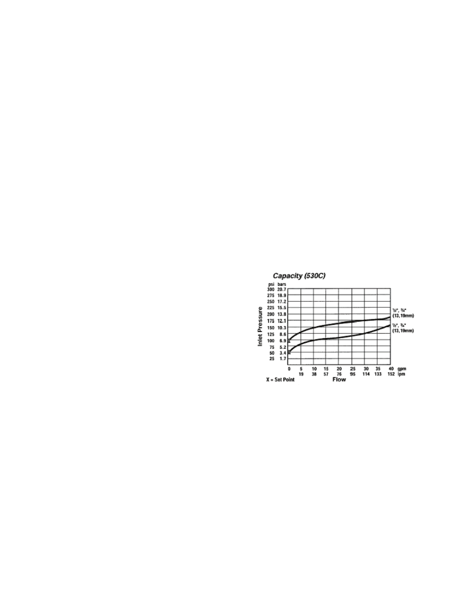
Pressure Relief Valve
Required pressure relief valve is installed in
the unit. This valve is set at 125 psig. Figure
1 shows inlet pressure versus capacity for
this pressure relief valve. See appendix for
additional information.
Figure 1 - Pressure Relief Valve
Manual and Automatic Air Vent
A manual air vent is supplied in chillers
without pumping packages. With a pumping
package option, there is an air scoop
installed at the high point of the system.
The air vent valve must be in the proper
position for operation. Ensure that the small
vent cap on the automatic air vent is
loosened one to two turns from the closed
position, allowing air to be vented from the
system. It is advisable to leave the cap on to
prevent impurities from entering the valve.
See appendix for additional information.