Caution – AAON LC-054 User Manual
Page 41
41
4. Position the adjoining flange or the pipe
to the Armgrip flange adapter and install the
remaining bolts. The two locking bolts
should be tightened first in order to position
the flange correctly.
Note: Care should be taken to ensure that
the gasket is not pinched or bent between
flanges.
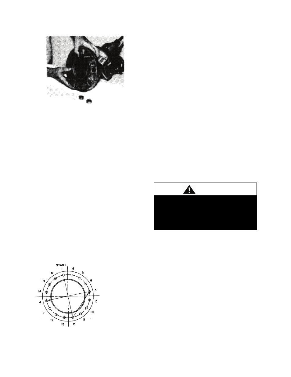
5. Tighten remaining nuts evenly by
following bolting instructions, so that the
flange faces remain parallel (as shown in the
figure labeled Recommended Bolt
Tightening Procedure).
Flange bolts should be tightened to 70 ft-lbs
torque minimum to assure firm metal to
metal contact. When raised face flanges are
sued, there will be a gap between the faces
of the outer diameter.
6. Flange gaskets are not interchangeable
with other mechanical pipe couplings or
flange gaskets.
Recommended Bolt Tightening Procedure
Field Conversion (Straight to Angle
Pattern Valve)
1. Open valve at least one complete turn.
2. Remove the body bolts from valve body
using Allen Key
3. Rotate one half of the valve body 180°
making sure the lower valve seat and O ring
stay in position. Inspect the O ring for any
cuts or nicks and replace if necessary
4. Replace body bolts and torque evenly to
70 ft-lbs.
Flow Measurement with the valve in the
Wide Open position:
Where approximate indication of flow is
acceptable the Flo-Trex valve can be used.
Step 1. Measure and record the differential
pressure across the valve.
Step 2. With valve in fully open position,
locate the differential pressure on the
Performance curve, and for the given valve
size in use, read the corresponding flow rate.
Flow Measurement with the valve in the
throttled position:
Step 1. The valve stem with its grooved
rings and positioning sleeve is the flow
indicator scale for the throttled position of
the valve.
Safety glasses should be worn.
Probes should not be left inserted
into fittings for long periods of time as
leakage may result.
CAUTION