Communication Concepts AN762 Application Note User Manual
Page 2
AR
C
HIVE INF
O
RMA
TI
O
N
PRODUCT TRANSFERRED T
O
M/A
–
COM
AN762
2
RF Application Reports
+
V
CC
-
R3
R1
Q1
Q2
R2
R4
C5
C4
C2
C1
T1
INPUT
50 Ω
L1
L2
C3
C8
L3
C10
C11
T2
+
-
OUTPUT
50 Ω
Q3
L4
-
C9
V
CC
+
TO PIN 2
C12
R12
R5
R8
R9
R6
1
10
6
8
7
9
5
4
3
2
MC1723G
D1
e
f
a
c
b
d
C6
E
+
R7
R11
R10
T3
D2
L5
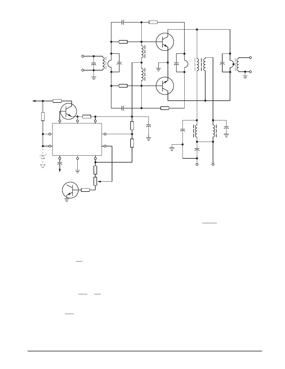
Figure 1. Basic Circuit of Linear Amplifier
In Class A the bias is adjusted for a collector idling current
of approximately one-half of the peak current in actual
operating conditions, and the conduction angle is 360
°.
In Class AB, (common for SSB amplifiers) the bias is set
for a low collector quiescent current, and the conduction
angle is usually somewhat higher than 180
°.
The required base bias current can be approximated as:
h
FE
I
C
,
where:
I
C
= Collector current, assuming an efficiency of 50% and
P
out
of 180 W is:
13.6
360
= 26.47 A.
V
CC
2P
out
=
h
FE
= Transistor dc beta (typical 30, from data sheet)
= 0.88 A
30
26.47
Bias current =
R12 shares the dissipation with Q3, and its value must
be such that the collector voltage never drops below
approximately
= 13.2
Ω).
0.88
(13.6 – 2)
2.0 V (e.g.
The MRF421 devices used for this design had h
FE
values on
the high side (45), and R12 was calculated as 20
Ω, which is
also sufficient for the lower power versions.
R5 determines the current limiting characteristics of the
MC1723, and 0.5
Ω will set the limiting point to 1.35 A,
± 10%.
For SSB operation, excluding two-tone testing, the duty
cycle is low, and the energy charged in C11 can supply higher
peak bias currents than required for 180 W PEP.
It is possible to operate the basic regulator circuit,
MC1723, at lower output voltages than specified, with
modified component values, at a cost of reduced line and
output voltage regulation tolerances which are still more than
adequate for this application. Temperature sensing diode D1
is added for bias tracking with the RF power transistors. The
base-emitter junction of a 2N5190 or similar device can be
used for this purpose. The temperature tracking within 15%
to 60
°C is achieved, even though the die processing is quite
different from that of the RF transistors. The physical
dimensions of Case 77 (2N5190) permits its use for the
center stand-off of the circuit board.