Archive informa tion archive informa tion – Communication Concepts EB27A Engineering Bulletin User Manual
Page 3
ARCHIVE INFORMA
TION
ARCHIVE INFORMA
TION
EB27A
3
RF Application Reports
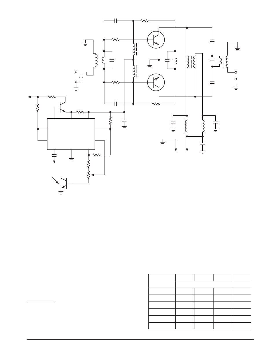
300-Watt Linear Amplifier Schematic Diagram
C1 — 100 pF
C2, C3 — 5600 pF
C4, C5 — 680 pF
C6, C7 — 0.10
µ
F
C11 — 470 pF
C12, C13 — 0.33
µ
F
C14 — 10
µ
F – 50 V electrolytic
C15 — 500
µ
F – 3 V electrolytic
C16 — 1000 pF
R1, R2 — 2 x 3.3
Ω
, 1/2 W in parallel
R3, R4 — 2 x 3.9
Ω
, 1/2 W in parallel
R5 — 47
Ω
, 5 W
R6 — 1.0
Ω
, 1/2 W
R7, R8 — 1.0 k, 1/2 W
R9 — 18 k, 1/2 W
R10 — 8.2 k, 1/2 W
R11 — 1.0 k Trimpot
D1 — 2N5190
L1, L2 — Ferroxcube VK200 20/4B
L3, L4 — 6 ferrite beads each,
Ferroxcube 56590 65/3B
Q1, Q2 — MRF422,
Q3 — 2N5990
T1, T2, T3 — See text
All capacitors except electrolytics and C16
are chips —
Union Carbide type 1813 and 1225, or
Varadyne size 18 or 14, or equivalent
+
V
CC
+
-
R3
R1
MOUNTED TO
HEATSINK
Q1
Q2
R2
R4
C4
C11
C2
C1
T1
INPUT
50
Ω
L1
L2
C3
C12
L3
C14
C15
C6
C5
C7
T2
+
-
OUTPUT
50
Ω
Q3
L4
V
CC
-
C13
T3
V
CC
+
TO PIN 2
C16
R5
R6
R9
R10
R11
R7
1
10
6
8
7
9
5
4
3
2
MC1723G
D1
R8
For production quantities, the braid in T
3
may be made
of brass or copper tubes with their ends soldered to pieces
of PC board laminate. See cover picture and Motorola
AN-749 for details.
The bandwidth characteristics of these transformers do
not equal those of the transmission line type, but they’re
much easier to duplicate.
The measured performance of the amplifier is shown in
figures 1, 2, and 3 and harmonic rejection data in table 1.
* A similar product is available from Fair-Rite Products Corp., Wallkill,
N.Y.,12589
Registered trademark of DuPont
PCB, chips capacitors, transformers T
1
, T
2
, T
3
, and ferrite beads
are available from: COMMUNICATIONS CONCEPTS, 2648 N. Ara-
gon Ave., Kettering, Ohio 45420. Telephone: (513) 294-8425.
Table 1. Output Harmonic Contents,
Measured at 300-W CW
(all test data taken using a tuned output,
narrow band signal source).
2nd
3rd
4th
5th
f (Mhz)
(dB below the carrier)
30.0
– 38
– 25
– 34
– 48
20.0
– 33
– 13
– 43
– 45
15.0
– 50
– 10
– 51
– 47
7.5
– 40
– 30
– 55
– 47
4.0
– 37
– 22
– 55
– 37
2.0
– 36
– 18
– 45
– 37