Archive informa tion archive informa tion – Communication Concepts EB27A Engineering Bulletin User Manual
Page 2
ARCHIVE INFORMA
TION
ARCHIVE INFORMA
TION
EB27A
2
RF Application Reports
Transformer Construction
For continuous operation at full power CW, it is
recommended that heat sink compound, such as Dow
Corning #340, be applied between the board surface and
R
3
and R
4
, and if possible have air circulating over the top
of the circuit board as well.
The effective base-to-base impedance, increased by the
RC networks is about 5 ohms at midband. As a result of
this and the 9:1 impedance ratio in the input transformer T1,
the input VSWR is limited to 1.9:1 or less across the band.
Transformer T2, in addition to providing a source for the
feedback and carrying the dc collector current, acts as the
rf center tap of the output transformer. To construct T2, wind
5 turns of 2 twisted pairs of AWG No. 22 enameled wire on
a Stackpole 57-9322 toroid (Indiana General F627-8Q1).
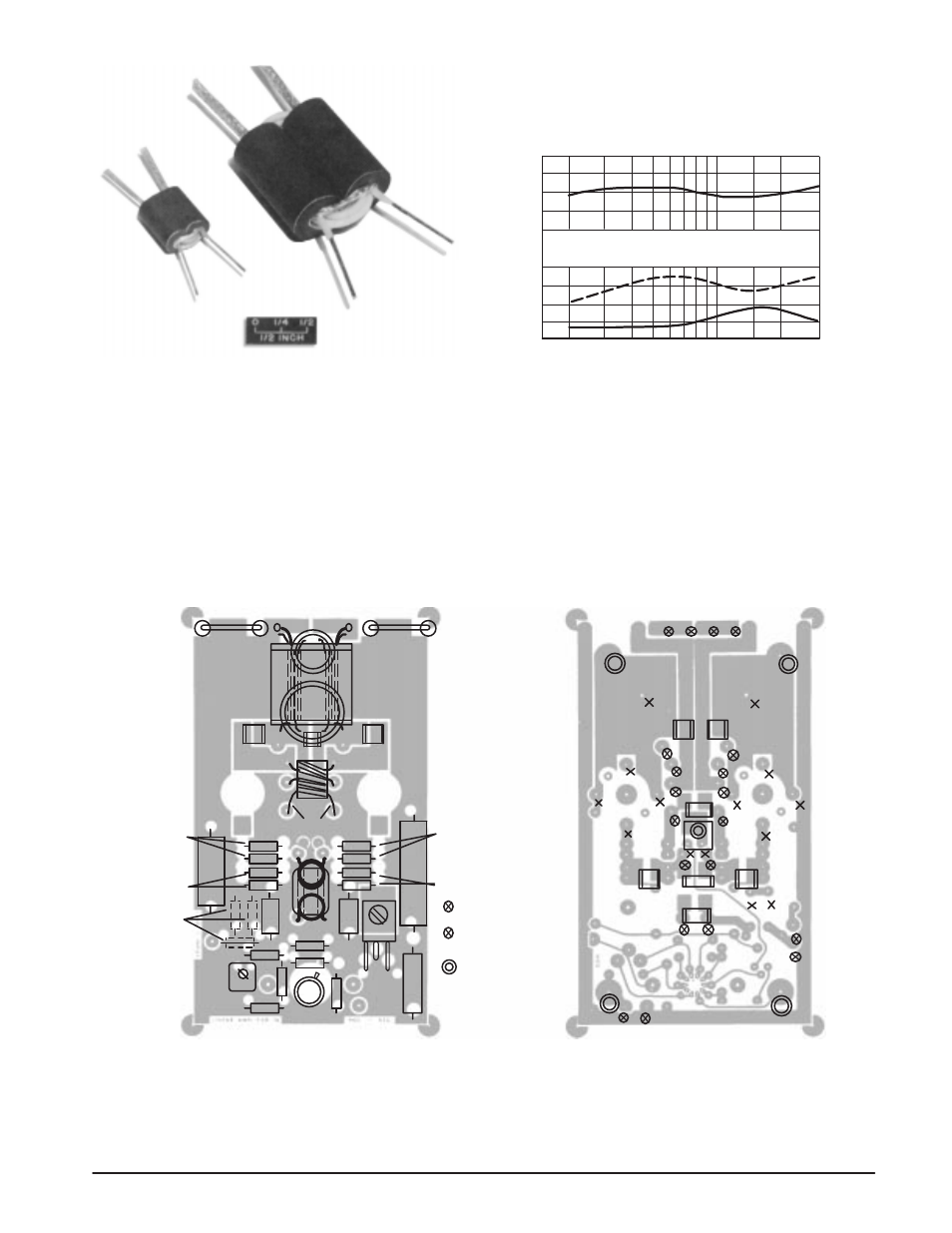
V
CC
= 28 V
P
OUT
= 300 W PEP
η
(%)
(DOTTED)
50
40
30
FREQUENCY (MHz)
30
20
15
10
7
1.5 2
3
5
POWER GAIN (dB)
VSWR (SOLID) 1
2
3
10
11
12
13
14
Figure 1. Collector Efficiency,
Power Gain and VSWR vs Frequencv
A Stackpole dual balun ferrite core 57-1845-24B is used
for T1. The secondary is made of 1/8
″
copper braid, through
which three turns of the primary winding (No. 22 Teflon
insulated hook-up wire) are threaded. The construction of
T3 is similar to that of T1. It employs two Stackpole 57-3238*
ferrite sleeves which are cemented together for easier
construction. The primary is made of 1/4
″
copper braid,
through which three turns of No. 16 Teflon
insulated wire
are threaded for the secondary .
A.
B.
C4
Optional
Input
Atten-
uator
R10 MC1723C
C2
C11
C1
D1
C3
C13
C12
Q1
Q2
C
C
T2
E
E
E
E
C5
C7
C6
L4
L3
L5
R4
R2
C15
R5
R3
R1
C14
L1
L2
T1
R6
C16
R11
R7
R9
R8
Q3
= Terminal Pins and
Feedthroughs
= Feedthrough
=
Eyelets.
= Stand Off’s