Install main assembly to wall – CHIEF TS218SU User Manual
Page 7
Installation Instructions
TS218SU
7
Install Main Assembly to Wall
-
Hollow
Concrete Block, Poured Concrete or Clay
Brick
WARNING:
Failure to provide adequate structural strength
for this component can result in serious personal injury or
damage to equipment! It is the installer’s responsibility to
make sure the structure to which this component is attached
can support five times the combined weight of all equipment.
Reinforce the structure as required before installing the
component.
WARNING:
The wall to which the mount is being attached
may have a maximum drywall thickness of 5/8" (1.6cm). Do
not install drywall anchors into the seam between drywall
pieces.
WARNING:
INSTALLING THE TS218SU INTO
UNDERRATED OR DAMAGED CONCRETE CAN LEAD TO
SERIOUS INJURY OR DAMAGE TO PRODUCT! Never
install the TS218SU into cracked, chipped or flaking
concrete.
1.
Determine mounting location.
2.
Measure 1" above desired center line and mark a hole at
desired mounting location. (See Figure 3)
IMPORTANT ! : Use a level to make sure main assembly
(J) is level when mounted to the wall!
IMPORTANT ! :
The TS218SU mount is designed to be
mounted to an 8" concrete, 8"x8"x16" concrete block or clay
brick wall.
3.
Drill one 8mm hole at location marked in Step 2. (See Figure
3)
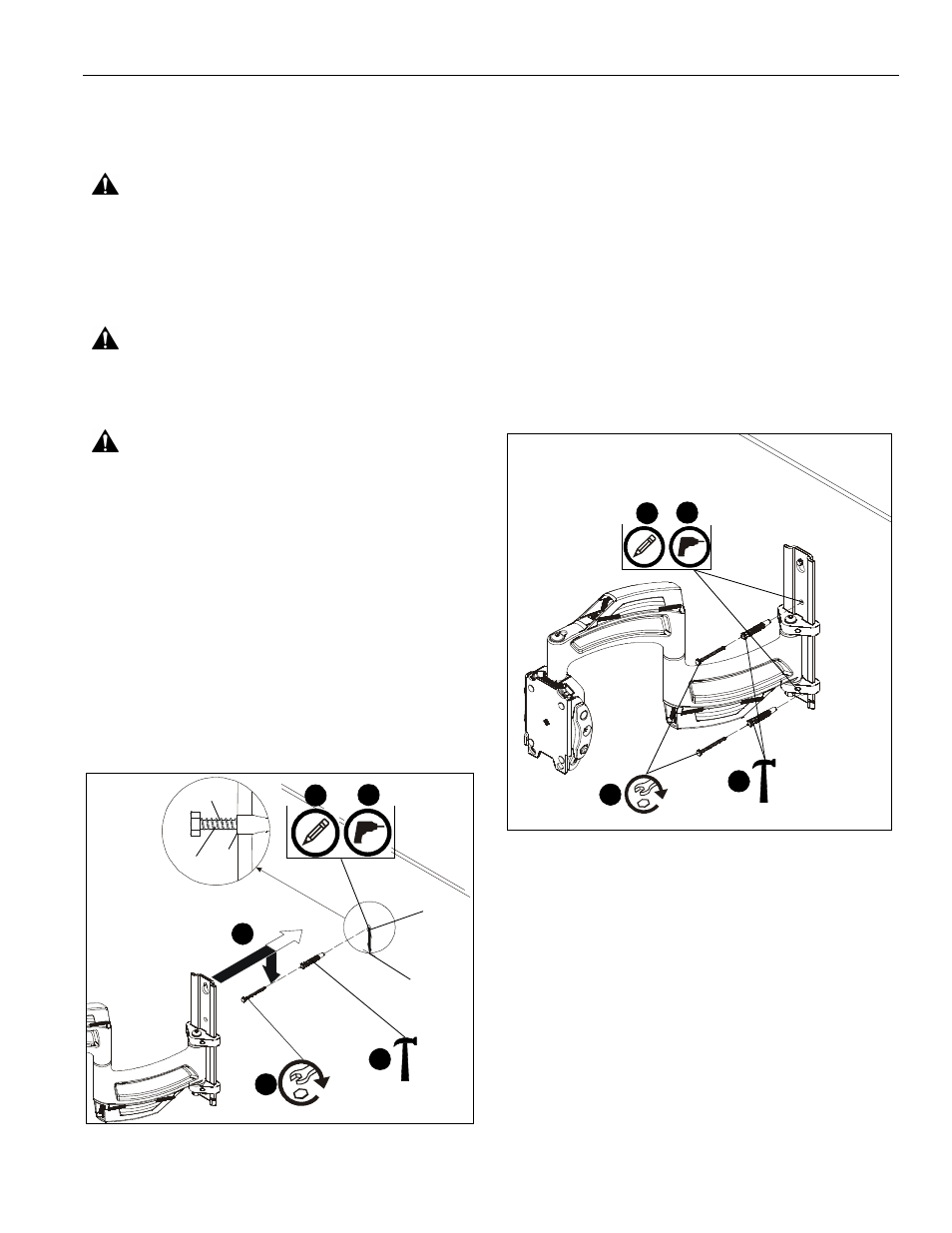
Figure 3
4.
Install one concrete anchor (G) into drilled hole. (See Figure
3)
5.
Install one 1/4 x 2 1/2" lag bolt (F) into concrete anchor (G),
leaving bolt hanging out 1/2" from the wall. (See Figure 3)
6.
Hang main assembly (J) onto lag bolt (F) by latching key-
shaped hole over top of bolt. (See Figure 3)
7.
Mark two holes at lower mounting hole locations. (See
Figure 4)
8.
Remove main assembly (J) from wall.
9.
Drill two 8mm holes at marked locations. (See Figure 4)
10. Install two concrete anchors (G) into holes. (See Figure 4)
11. Hang main assembly (J) back onto wall.
12. Install two 1/4 x 2 1/2" lag bolts (F) into concrete anchors (G)
to secure mount to wall. (See Figure 4)
13. Tighten all lag bolts (F) to fully secure mount to wall.
Figure 4
(F)
6
1/2"
screen
center
1" above
2
3
8mm
center
5
4
(G)
(F)
(G)
(F) x 2
12
7
9
10
(G) x 2