CHIEF TS218SU User Manual
Page 10
TS218SU
Installation Instructions
10
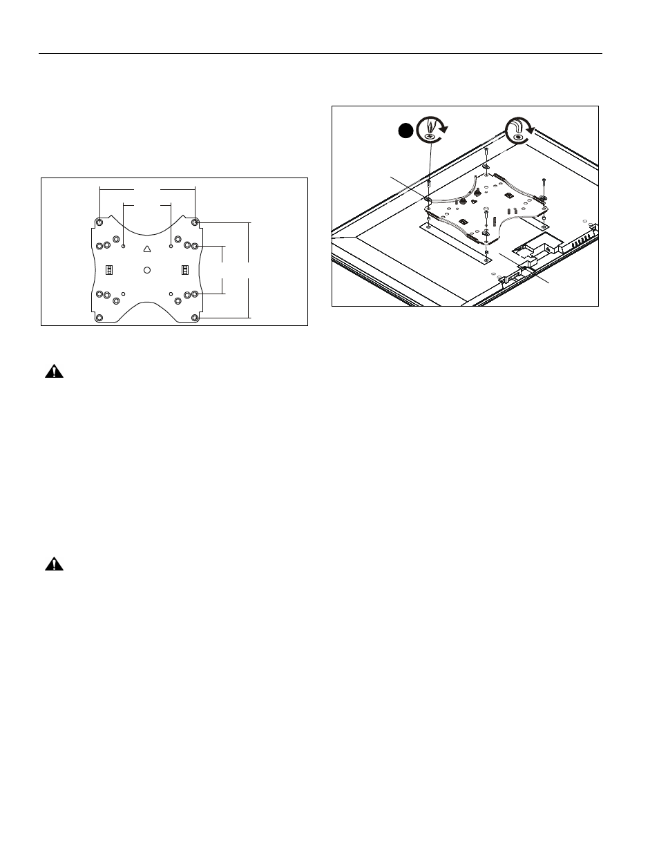
Attach Faceplate to Display Without Interface
Brackets (100x100 or 200x200 or 100x200 hole
patterns)
1.
Lay display face down on protective surface.
2.
Determine hole configuration to be used on faceplate. (See
Figure 10)
NOTE:
Displays may be mounted in a landscape or portrait
position in each of these configurations.
Figure 10
CAUTION:
Using screws of improper diameter may
damage your display! Proper screws will easily thread into
display mounting holes.
3.
Select screw diameter by examining hardware (A-D) (4mm,
5mm, 6mm or 8mm) and comparing with mounting holes on
display. (See Figure 11)
4.
Select spacers: (See Figure 11)
•
If mounting holes are not recessed and faceplate
(H) can lay flat against display, then no spacers
are required.
•
If mounting holes are recessed, or if protrusions
prevent faceplate (H) from laying flat, then
spacers (E2) must be used.
CAUTION:
Using screws of improper length may damage
your display! Proper screws will have adequate thread
engagement without contacting bottom of display mounting
holes.
5.
Select screw length: (See Figure 11)
•
Using your hand, insert SHORTEST length screw
of selected diameter (A1, B1,C1 or D1) through
universal washer (E1) or M8 washer (E3),
faceplate (H), selected spacer (E2, if required),
into display mounting hole. Do NOT thread screw
into hole at this time.
NOTE:
If using M8 button head cap screws (D1-D3), use M8
washers (E3) rather than universal washers (E1).
•
Proper screw length requires base of screw head
to protrude above flat washer a distance equal to
or greater than the screw diameter. If screw
length is inadequate, select longer screw. Select
shortest screw which will protrude the required
distance.
6.
Use selected screws and spacers to connect interface
brackets to back of display. (See Figure 11)
Figure 11
100 200
200
100
1 2
3
1 2
3
3
2
1
3
2
1
(200x200 configuration shown)
(A-C) x4 or
5
(D) x4
(E1) x 4 or (E3) x 4
(E2) x 4
(with recessed holes)