CEMB USA C65 (F) User Manual
Page 14
I 0426 - 14
I 0426 - 15
2
4
6
7
GB
GB
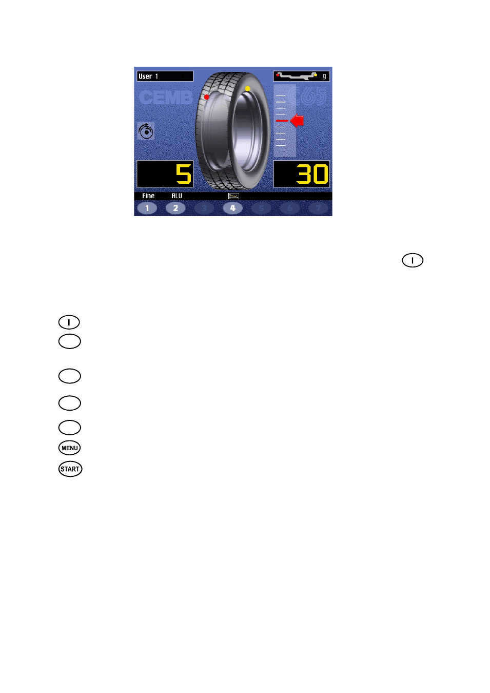
5.5 - Result of measurement
After performing a balancing spin, the unbalance values are displayed as well as arrows useful for positioning the
point of application of the correction weight. After positioning the wheel, apply the weight in the 12 o’clock position.
If the unbalance is less than the chosen threshold value, the “OK” appears instead of the unbalance value to indicate,
on that particular side, the wheel is in tolerance; the residual unbalance can be displayed by pressing button
with an accuracy of 0.5 g (0.1 oz).
The following buttons are enabled:
Display of residual unbalance
Selection of correction mode (DYNAMIC, STATIC, ALU1, ALU2, ALU3, ALU4, CTS). When the mode
is changed, the unbalance values are recalculated automatically on the basis of the previous spin
(
ALU
AND STATIC MODES
).
Eccentricity measurement graph (optional).
The symbol appearing above the button changes to
red if the eccentricity is excessive.
Split control for splitting of unbalance over presettable components (
“SPLIT” CONTROL
).
Button only
enabled in STATIC or ALUS correction.
Indication of the longitudinal position of the unbalance
(
INDICATION OF EXACT CORRECTION
WEIGHT POSITION
)
is enabled
For selection of special functions
Balancing spin.
N.B..
If the machine remains on this screen without being used for more than the time preset in the Setup
parameters (6), the screen automatically returns to the screen-save.