Starting, English – CEMB USA C71_2 SE evo (B) User Manual
Page 7
7
Use and maintenance manual Rev. 10-2012
ENGLISH
Starting
3.
Starting
WARNING
b
efoRe
sWITchING
oN
The
mAchINe
,
mAke
suRe
ThAT
All
The
coNNecTIoNs
descRIbed
IN
The
INsTAllATIoN
chApTeR
hAve
beeN
mAde
coRRecTly
.
T
he
folloWING
opeRATIoNs
INvolve
A
poTeNTIAl
RIsk
foR
The
opeRAToR
,
GIveN
The
pReseNce
of
volTAGe
oN
The
equIpmeNT
. T
he
p
eRsoNAl
p
RoTecTIve
e
quIpmeNT
descRIbed
IN
The
INsTAllATIoN
mANuAl
musT
be
WoRN
ANd
WoRk
musT
be
doNe
WITh
due
cARe
ANd
ATTeNTIoN
.
o
peRATIoNs
mAy
oNly
be
peRfoRmed
by
A
specIAlIsed
TechNIcIAN
.
Before powering the machine, carry out the following
checks:
1. check that the balancing machine touches the floor
at the three support points;
2. make sure that all the parts of the balancer are cor
rectly connected and fixed;
3. make sure that the parameters (voltage and frequency)
of the mains power supply are compatible with those
indicated on the rating plate of the balancer;
4. make sure the power cable is correctly connected;
5. make sure the machine shaft and flange hole are
clean.
cAuTIoN
A
Ny
TRAces
of
dIRT
mAy
AffecT
bAlANcING
AccuRAcy
.
6. To switch on the balancer press the switch on the
left-hand side of the machine.
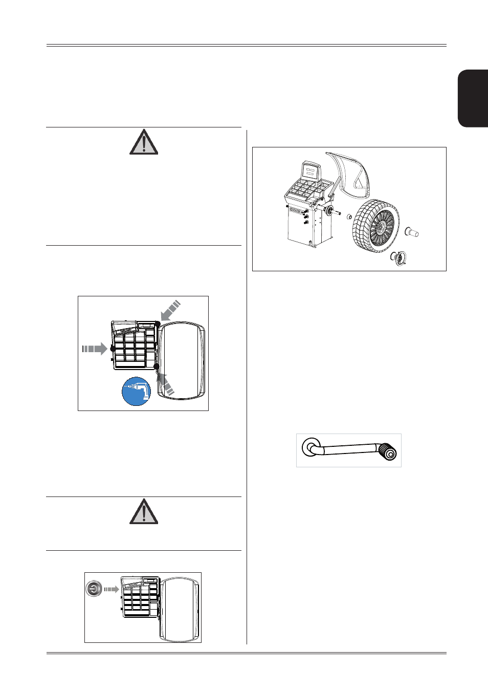
7. Position the wheel on the terminal with the inner part
facing the balancer;
8. Firmly attach the wheel to the balancer shaft using
the lock nut. In the pneumatic version, use the spe
cific collar provided. For operation of the spindle
with pneumatic locking (constant thrust air spring)
connect the wheel balancer to the compressed air
mains. The connection fitting is located at the back
of the machine. At least 8 Kg/cm
2
(~ 0.8 MPa; ~
8 BAR; ~ 115 PSI) pressure is needed for correct
operation of the release device.
9. In the normal version, the pedal controls a mechani
cal brake which facilitates locking the locking ring
and positioning the wheel for correction.
In the pneumatic version, it allows fastening/relea
sing the wheel on the adapter using the collar. The
pedal has two stable positions: upper position for
unlocking; lower position for locking the wheel.
10. The wheel is automatically locked when reaching
the correct angular position for weight application
on the inside and outside, turning it slowly by hand.
To unlock the wheel, turn it hard to move it from the
correct correction position.
11. At this point, you can read the tyre measurements
and perform balancing.