3 modifying set dimensions, 4 static & combined modes, 2 measurement result – CEMB USA C71_2 SE evo (B) User Manual
Page 12
12
FI
FE
Use and maintenance manual Rev. 10-2012
ENGLISH
Slowly close the wheel guard until a “beep” is heard.If
“AUTOMATIC START” is enabled when the guard is closed,
the balancing machine performs a cycle to measure the
imbalance, otherwise the width value just acquired is shown.
Press the
button to perform a spin.
5.1.3 Modifying set dimensions
If the wheel dimensions have been entered incorrectly,
the parameters can be modified without repeating the
balancing spin by pressing for 2 seconds :
access parameter modification
→
(select
to modify: (a) distance, (b) width, (d)
diameter
In the case of standard weights:
(a)distance,(b)width,(d)diameter
In the case of adhesive weights:
(a1) inside distance,(a2) outside distance,(d1) inside
diameter,(d2) outside diameter
press
to select (a) (b) or (d)
→
to recalculate the unbalance
or:
pull out the gauge to repeat the measurement
→
to obtain the new measurement.
5.1.4 Static & combined modes
After calibration as per
PRESETTING OF WHEEL DIMENSIONS
,
it is possible to modify the position of the correction weights
using the
buttons.
STATIC: Select by pressing
(5E)
Balancing of light alloy rims with application of adhesive
weights on the shoulders of the rims.
Combined balancing: adhesive weight on the outside and
clip-on weight on the inside.
Combined balancing: adhesive weight on the inside and
clip-on weight on the outside.
5.2
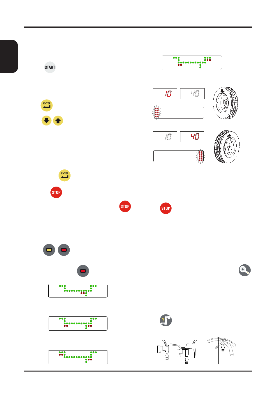
MEASUREMENT RESULT
After performing a balancing spin, the amounts of unbal-
ance are shown on the digital readouts. The illuminated
LEDs 3 and 4 indicate the correct angular position of the
wheel to mount the counterweights. If the wheel clamp
option is enabled (see
MENU
), the wheel is automatically
clamped in the correction position.
Pressing
the spindle can be locked/released in any
position to facilitate mounting the wheel (see
MENU
).
If LSr option = OFF:
after positioning and locking the wheel, apply the weight
vertically at the top.
If LSr option = ON:
apply the clip-on weights at 12 o’clock. If using adhesive
weights, when the correction position is reached, the laser
turns on indicating the point where to apply the adhesive
counterweight.
For unbalance within tolerance 0 (zero); using
values within tolerance can be viewed.
5.3 EXACT POSITIONING OF THE ADHESIVE
WEIGHT BY MEANS OF THE GAUGE WITH
CLIPS
▪ Press
if using the correction method with adhe-
sive weights on the inside of the rim
Use of the wheel balancer