Split function, Unbalance resolution), 4 split function (unbalance resolution) – CEMB USA C71_2 SE evo (B) User Manual
Page 13
13
1
2
1
2
1
2
2
1
2
1
2
1
Use and maintenance manual Rev. 10-2012
ENGLISH
▪ Fit the correction weight in the specific gauge seat with
the adhesive part facing upwards
▪ Bring the wheel into correct angular position for the
plane to be corrected
▪ If the wheel clamp option is enabled (see
MENU
),the wheel
is automatically clamped in the correction position.
▪ withdraw the gauge until the correction plane indication
arrows turn green
▪ If the buzzer is enabled (see
MENU
), the attainment
of the weight application distance is accompanied by
a beep.
▪ Rotate the gauge until the correction weight adheres to
the rim
▪ the fact that the weight application position is no longer
vertical is automatically compensated.
- INSIDE CORRECTION POSITION
- OUTSIDE CORRECTION POSITION
To cancel the function, press the
button again.
5.4
SPLIT FUNCTION
(unbalance resolution)
The SPLIT function is used to position the adhesive weights
behind the wheel spokes (angle > 18°) so that they are no
longer visible (for alloy rims). Use this function in the ALU
or STATIC mode where the adhesive weight is applied to
the outer side of the rim.
Enter the wheel dimensions in the ALU S mode and press
START.
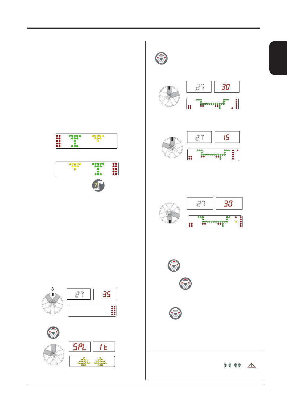
If LSr option = OFF
a. Turn the wheel to the outer side unbalance correction
position.
b. Move one of the spokes to 12 o’clock (e.g.: 1) and
press
c. Following the direction of rotation indicated by the
position LED’s, move spoke 2 to12 o’clock and press
. The value to use for correction in position 2
is displayed.
d. Move spoke 1 to the correction position as indicated
by the position LED’s
Only standard version
If the “OPPOSITE POSITION” function is enabled (see the
relative paragraph), the bottom correction position (at 6
o’clock) is indicated by the central LED coming on for each
phase column.
Only SE version
If LSr option = ON
▪ Position the static unbalance or outside ALUS in the
in the correction position:
▪ press
and hold down until the laser points
to the spoke where you want to correct
▪ release the
button
▪ turn the wheel in the unbalance rotation direction
indicated on the display until the second spoke is in
the position indicated by the laser and press the
button
▪ position the wheel as indicated by the LEDs. The un-
balance is indicated on the display.
To return to the normal unbalance indication press any
button.
INfoRmATIoN
The spoke-to-spoke distance must be a minimum of 18°
and a maximum of 120° (if not, errors
,
or
appear). Spokes with irregular or inconstant angles can
be compensated.
Use of the wheel balancer