2 alus wheels – CEMB USA C218 User Manual User Manual
Page 10
10
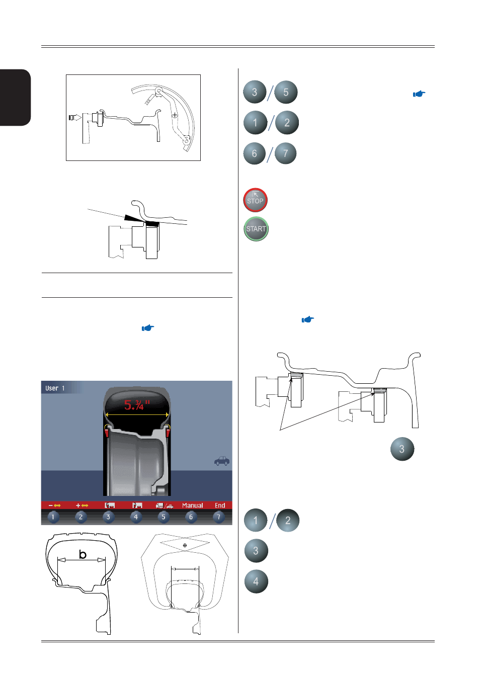
Pos B
Pos A
FI
FE
FI
b
b
Use and maintenance manual Rev. 04-2011
ENGLISH
b) Adhesive weight: in the position indicated below.
INDICATION
Always use the round part of the striker plate.
Hold the gauge in position for at least 2 seconds.
If the acoustic signal is enabled (
ACOUSTIC SIGNAL
), the
acquisition of the dimensions is accompanied by a “beep”.
Set the distance+diameter gauge to the rest position: the
current width value is displayed inside the tyre.
The other enabled buttons are:
Select the type of weight to apply (
CORRECTION METHODS
).
User
call/save
control.
Set the nominal width, which is normally
shown on the rim, or measure the width
“b” with the caliper gauge provided.
Return to initial frame.
Launch
balancing.
5.2.1.2 ALUS wheels
After the measurement performed for the FI inner side, as
indicated in the fi gure below, pull out the gauge again to
store the data for the FE outer side; choose position A or B
at your choice. Keep this position for at least 2 seconds. The
counterweight symbols change colour. When the acoustic
signal is enabled (
ACOUSTIC SIGNAL
), the acquisition is
accompanied by a “beep”.
After having detected the dimensions, use the
key to
indicate the type of correction selected for the inner side.
The following buttons are enabled:
Management of save user recall
Selection of clip or adhesive weight for
inside.
Only for automatic width option:
The
L.T. key (LIGHT TRUCK) used to
improve the dimensional calibration of
large diameter wheels such as off-road,
trucks, wheels which protrude signifi can
tly from the rim. Press the L.T. key, after
distance measurement, immediately before
Use of the wheel balancer
Position of adhesive weights
Position of adhesive
weights