J&M GC-24T Assembly User Manual
Page 45
-45-
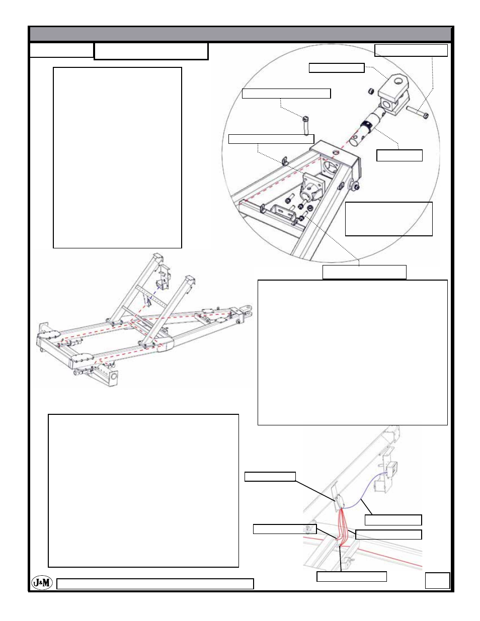
STEP - 82
Feed the Weigh Bar wire through
the left side of the A-frame, exit-
ing out the grommet hole directly
behind the front leg weldment.
Use 3/4” x 3” Gr 5 bolts to attach
the Weigh Bar Weldment to the
A-frame.
Carefully slide the Weigh Bar
into the Weigh Bar Weldment
and attach it with 1” x 4 1/2” Gr 5
Bolt and locknut. Do not damage
Weigh Bar wire.
Attach Swivel Hitch with 1” x 5
1/2” Gr 5 Bolt and locknut to the
Weigh Bar.
3/4” x 3” Grd 8 Bolt
Weigh Bar
Weigh Bar Weldment
Swivel Hitch
1”x 4 1/2” Grd 5 Bolt
Note: Run wire from
weigh bar through left
side of frame
Feed wires from the right side weigh bars as
shown, through adapter plate then through the
frame.
Feed wires from left side weigh bars as
shown, through adapter plate, frame, then
through the cross bar on the frame (as shown
in diagram to the left).
Now all five wires should be ran to the left
hole above the center cross brace in the A-
frame.
Junction Box
Indicator Wire
Right Weigh Bars
Left Weigh Bars
Hitch Weigh Bar
On the Junction Box there are 7 connectors.
The connector that is on the left side of the
Junction Box needs to be plugged. To install
untighten the connector, insert plug, then re-
tighten.
Run indicator wire from back of the indicator
to the front center connector of the junction
box.
Run all five weigh bar wires to the Junction
-Box. *See image on next page.
-Scale Option-
*Right & Left determined by facing the rear of cart.
1”x 6” Grd 5 Bolt