Iii. settings of special camera – I-View SDCI-220 Indoor Speed dome User Manual
Page 8
8
III. Settings of Special Camera
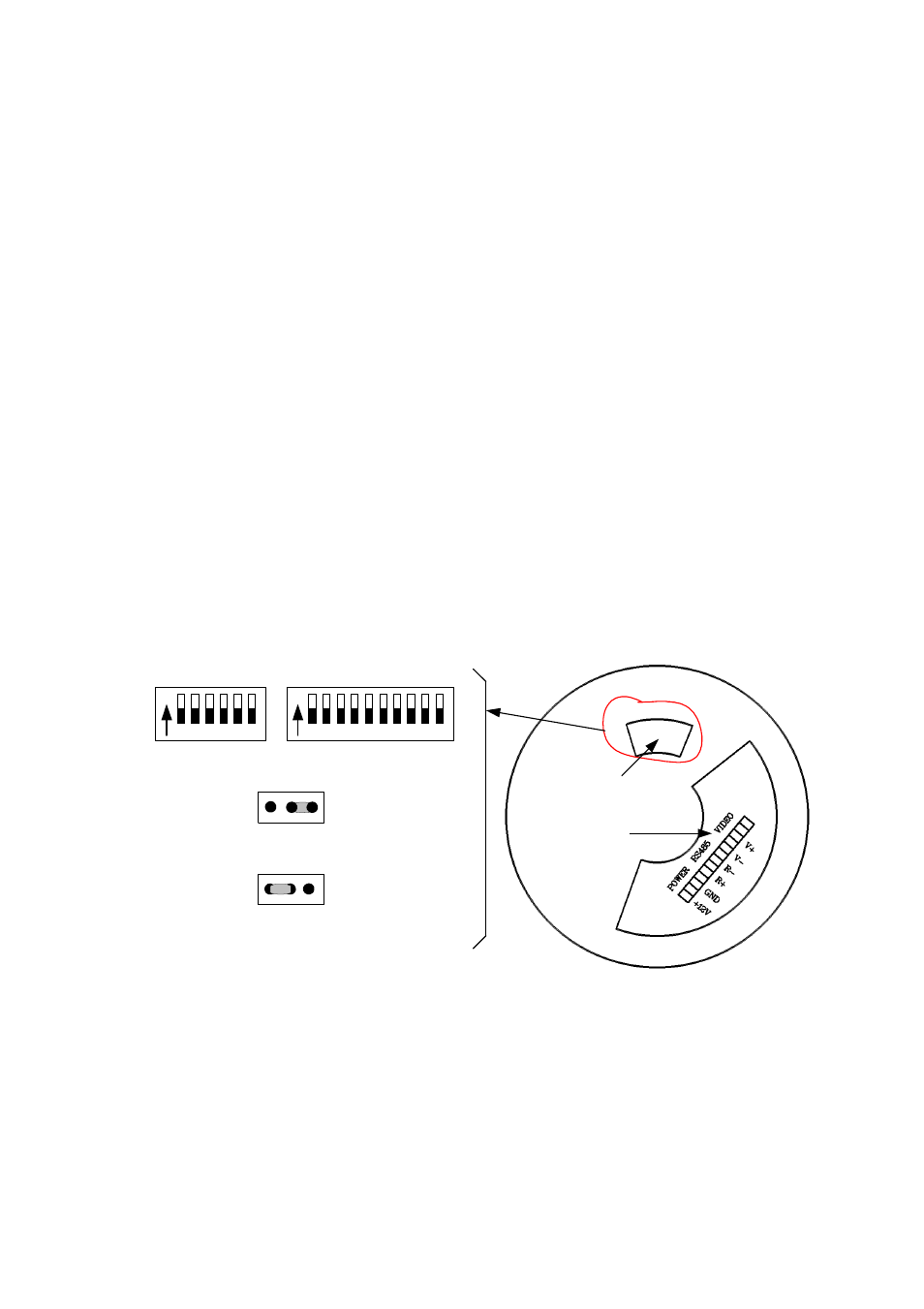
Before installing the spherical camera, please confirm the communication
protocol and baud rate the master controller in the system uses, then set the
coding switches on the back of the camera to be identical with that of the
system in which SW1 is for address of the spherical camera and SW2 is for
communication protocol and baud rate (see attached tables 1,2 and 3).
JP1 is jumper for the terminal resistor.
JP1 is the 120
Ω terminal resistor for RS485 Bus. When short-circuit
terminal is set between “1-2”, the 120
Ω terminal resistor is opened while
it is set between “2-3”, the resistor is connected. Take care that on RS 485
Bus only one farthest spherical camera has the terminal resistor connected
while other devices should have their terminal resistors opened.
3
1 2
JP
Protocol Select
ON
1 2 3 4 5 6 7 8 9 10
SW1
Speed Dome Address Select
ON
1 2 3 4 5 6
SW2
120Ω term inal resistor is connected on R S485 B us
120Ω term inal resistor is opened for R S485 bus
JP
3
1 2
ID-CODE Set
System
control wire