I-View DM-650-F0409 Vandal Proof Dome UTP Camera User Manual
I-View Camcorders
1
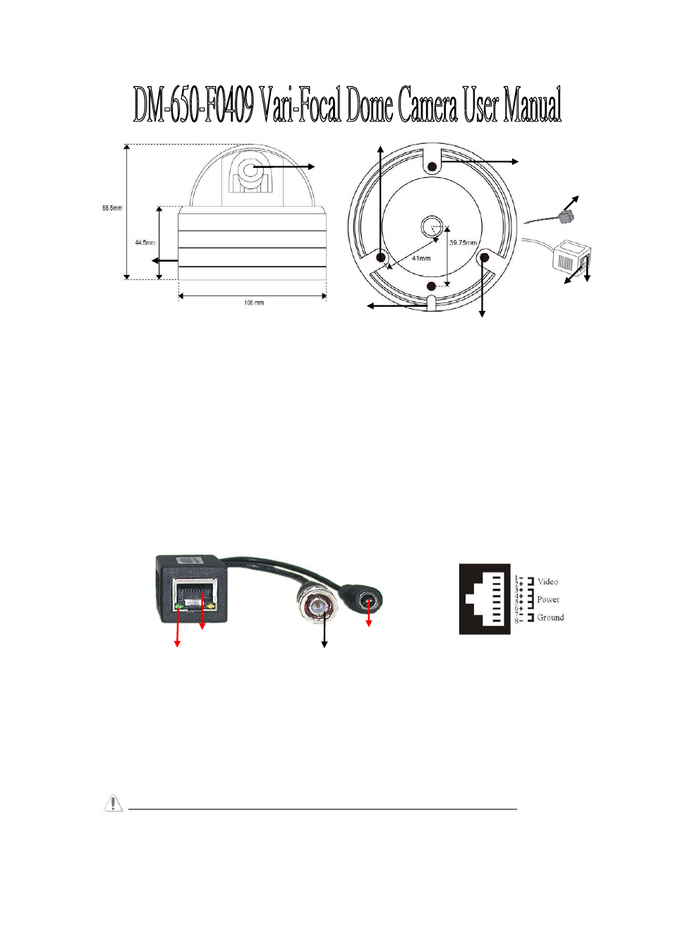
DM-650-F0409 Dome Camera Function Description:
1.) Lens: 4-9mm Vari-Focal Lens. Provide 2.8-12mm Vari-Focal Lens as alternative choices.
2.) Screw: Screw the camera housing.
3.) Mounting Hole: There are 3 holes to fix the camera housing on the ceiling.
4.)
Gutter: To fix the wire cable of camera.
5.) LED: Power indicator, Green LED On: Power on. Green LED Off: No Power. Yellow LED: Reserve.
6.) RJ-45 connector: To transmit Power and Video signals via UTP cable. Please refer to the RJ45 pin assignment.
7.)
Socket cable: To Connect OSD control cable (Optional) for camera parameters setup.
PTT-140VPM Function Description: (On DVR site)
1.) Power Plug: Connect DC 12V-18V power source input and provide power output for camera.
2.) BNC Cable: For video output to DVR.
3.) RJ-45 connectors: To transmit Power and Video signals via UTP cable.
Please refer to the pin assignment.
4.) LED: Power indicator, LED On: Power on. LED Off: Not enough power or No Power.
5.) RJ-45 pin Assignment: Connect the 4-pair UTP cable between DVR site and camera end for video/power
transmission.
WARNING: This camera MUST use DC 12V-18V power adapter for power transmission.
V1.0
Male BNC
RJ45 Connector
Power Indicator
Power Plug
PTT-140VPM
RJ45 Pin Assignment
3
1
3
3
4
2
6
5
7