I-View DM-650IR-F0312 IR Dome Vandal Proof UTP Camera User Manual
I-View Camcorders
1
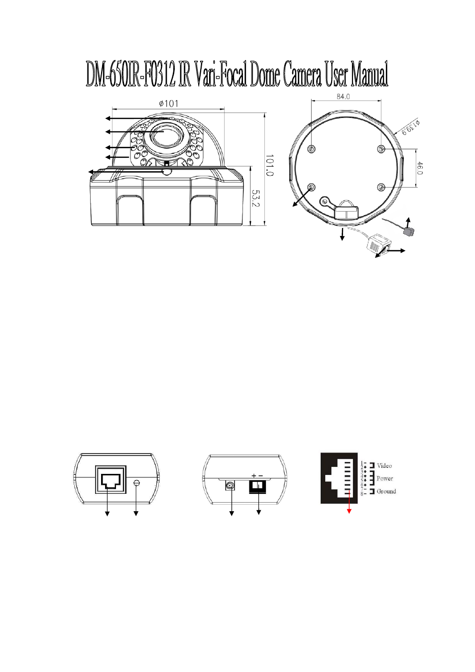
DM-650IR-F0312 IR Dome Camera Function Description:
1.) Sensor: To detect the luminance of environment, the LED will be turned on when lower than 0.5 Lux.
2.) Lens: 2.8-12mm Vari-Focal Lens.
3.) IR LED: Built in 30 pcsψ5 IR LED, the illuminate distance up to 20 meters.
4.) Cover: The vandal resistances transparent cover
to avoid the damage by force.
5.) Screw: To fix the housing body and cover.
6.) Mounting Hole: There are 4 holes to fix the camera housing on the ceiling.
7.)
Side Hole: To lose the screws cap for wiring if the cable not through ceiling.
8.) LED: Power indicator, Green LED On: Power on. Green LED Off: No Power. Yellow LED: Reserve.
9.) RJ-45 connector: To transmit Power and Video signals via UTP cable. .
10.) Socket cable: To Connect OSD control cable (Optional) for camera parameters setup.
PRX-120VP Function Description: (On DVR site)
1.) RJ-45 connector: To transmit Power and Video signals via UTP cable. Please refer to the pin assignment.
2.) LED: Power indicator, LED On: Power on. LED Off: Not enough power or No Power.
3.) BNC Cable: For video output to DVR.
4.) Terminal Blocks: Power input for power transmission. Accept power range DC 24V or AC24V-28V.
5.) RJ-45: Connect the 4-pair UTP cable between DVR site and camera end for video/power transmission.
V1.0
RJ-45 Connector
Pins Assignment
Front Panel
PRX-120VP Back Panel
5
1 2
3 4
1
8
6
3
9
4
10
2
5
7