Figure 16 – sequence of cycle on demand operation – DE-STA-CO VARI-PAK DC CONTROL User Manual
Page 17
15
VIII. APPLICATION WIRING DIAGRAMS (Reversible Models)
P/N 92A61633020000 (120 VAC) – P/N 92A61633040000 (240 VAC).
Reversing models carry out the same functions as the unidirectional models except they can
be made to index in both the forward and reverse direction. A special circuit APRM® pro-
vides a lockout feature that prevents catastrophic damage to the drive if a “Reverse” com-
mand is given during “Forward” operation (and vice versa). The reversing drives contain two
additional positions on the terminal block: “Run Rev” and “Jog Rev.” The stop logic com-
mand is made with a normally closed (NC) contact.
Note: The sense of the stop logic can be changed from normally closed (NC) to nor-
mally open (NO) by placing jumper JS in the “NO” position.
The wiring diagrams on page 16 illustrate typical logic circuits. Many other configurations are
possible. Consult factory if help is needed.
IX. OPERATION
WARNING! Read Safety Warning on page 2 before attempting to operate the
control or severe injury or death can result. Failure to follow the Safety
Warning Instructions may result in electric shock, fire or explosion.
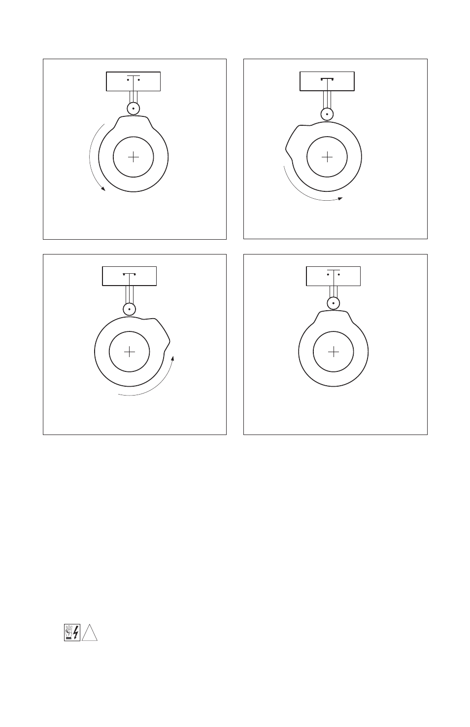
ROTATION
OF CAM
CONTACT IS OPENING
LS1
LS1
CONTACT CLOSES
1) CLOSE START BUTTON TO INITIATE
CYCLE (MOMENTARY CLOSURE)
2) CAM ROTATES, LS1 CONTACT CLOSES
CLOSED
CONTACT REMAINS
LS1
LS1
CONTACT OPENS
1) CAM CONTINUES TO ROTATE THROUGH
CYCLE, LS1 REMAINS CLOSED
4) CAM ROTATES UNTIL LOBE UNTIL LS1 CONTACT,
DRIVE BRAKES TO A STOP. CLOSE MOMENTARY
START BUTTON TO INITIATE NEW CYCLE.
FIGURE 16 – SEQUENCE OF CYCLE ON DEMAND OPERATION
!