DE-STA-CO VARI-PAK DC CONTROL User Manual
Page 15
13
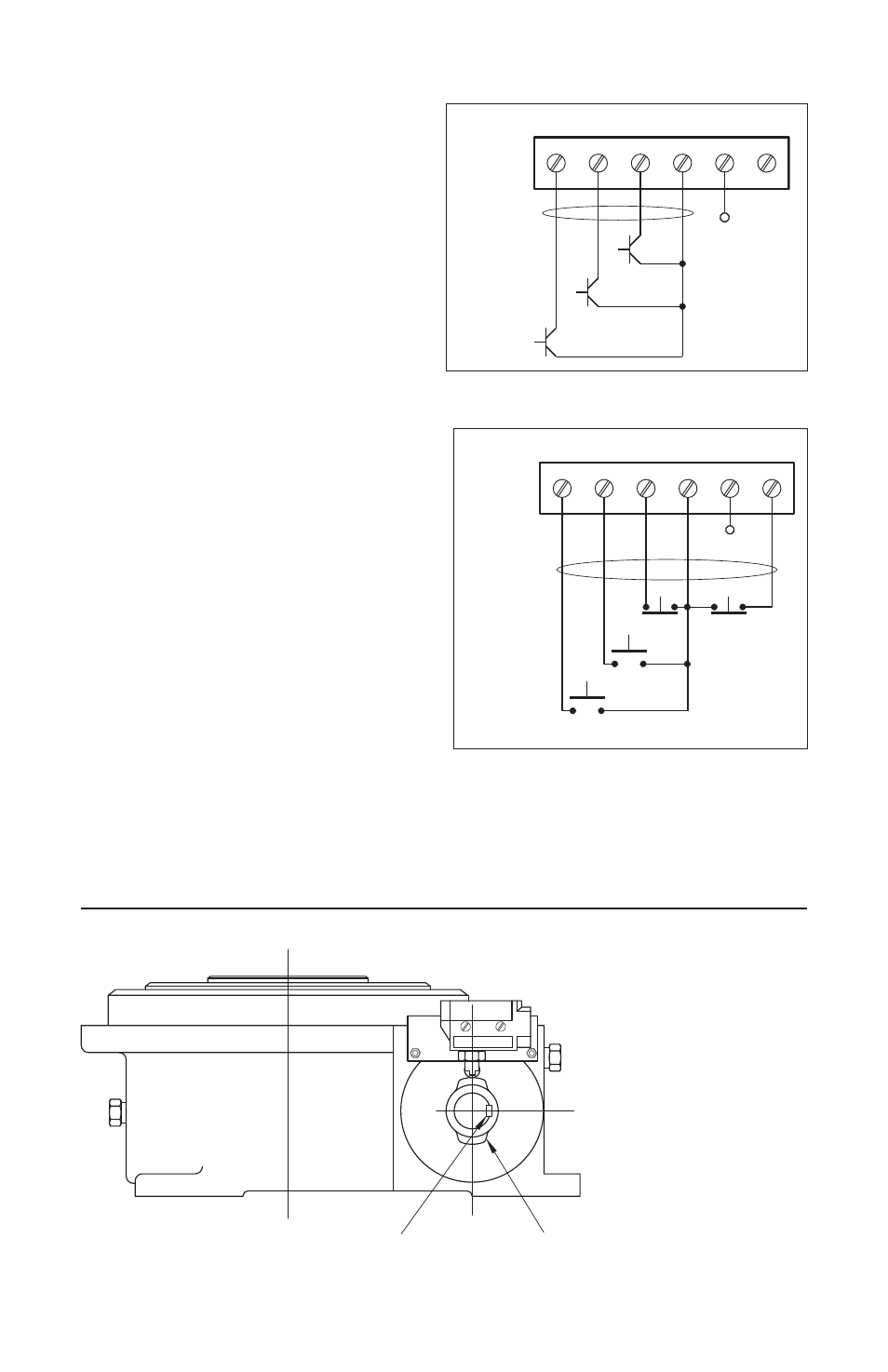
Capable of switching 30 VDC, at 24 mA,
with an off-state leakage current of less
than 1 mA. (See figure 12.) Warning!
Do not ground or short +24V to COM or
return on TB1. Do not use +24V for
other than open collector sensors. (See
figure 12.)
Example 2: For optimum operation,
contacts used on logic inputs should be
rated for low-level logic switching (i.e.
gold contacts). (See figure13.)
Example 3:
“Cycle on Demand” –
Important Information
In a “Cycle on Demand” application, the
CAMCO Index Drive will make one com-
plete cycle of movement of table or con-
veyor and then dwell until it receives an
external signal from the machine’s con-
troller or operator to start again. If motor
receives a signal to start while the CAMCO
Index Drive is in its dwell position, the
motor will accelerate from a paused posi-
tion to full speed during one half of the
dwell of the main index cam. When the
motor has reached its maximum speed
and is no longer accelerating, the motion of
the CAMCO Index Drive can start. As the
Indexer re-enters its dwell portion of the
main cam, the signal cam located on the
camshaft of the CAMCO Index Drive will
actuate the limit switch to signal a stop.
(Note: Due to time delays, the signal cam
may have to signal a stop some degrees
before the index drive actually enters the dwell.) It is important that the motor is made to stop
while in the dwell of the main cam. Stopping in any other position could damage the control or
the Index Drive! Read all the instructions carefully in order to familiarize yourself with your new
CAMCO Index Drive. (See figures 14A, 14B and 14C.)
RUN
JOG
STP
RTN
+24V COM
NOTE: JUMPER
"JR" MUST
STOP
JOG
START
BE IN THE
"F" POSITION
+V
See section IV,
items 1-4,
on page 9
FIGURE 12 – SOLID STATE SWITCHING
RUN
JOG
STP
RTN +24V
COM
NOTE: JUMPER
"JR" MUST
BE IN THE
"O" POSITION
RTN
STOP
JOG
START
+V
See section IV,
items 1-4,
on page 9
FIGURE 13 – CONTACT SWITCHING
Type II Extra
CAM LOBE
Keyway
A standard Roller Gear unit
with the CAM & Limit Switch
mounted on the correct key-
way position directly opposite
of the output shaft, 90º (clock-
wise) from the CAM Lobe.
The CAM & Limit Switch may
also be mounted on the
reducer. If the unit has a
“Type II” motion, a special
Limit Switch CAM is needed
with one extra Lobe, 180º
from the first Lobe (as shown).
Note: On some RDM units
(such as the 601 RDM), the
CAM & Limit Switch is
mounted at an angle.
FIGURE 14 – CORRECT KEYWAY POSITION FOR CAM & LIMIT SWITCH ASSEMBLIES
FIGURE 14A – ROLLER GEAR UNIT