Table 3 – selectable jumper reference chart – DE-STA-CO VARI-PAK DC CONTROL User Manual
Page 10
8
II.
MOUNTING
Mount the control in a vertical position on a flat surface. Be sure to leave enough room below
the bottom of the control to allow for the AC line and motor connections and other wiring that
may be necessary. Care should be taken to avoid extreme hazardous locations where phys-
ical damage can occur. Note: Do not use this control in an explosion proof application.
If the control is mounted in a closed, unventilated cabinet, remember to allow for proper heat
dissipation. If full rating is required, a minimum enclosure size of 12” W x 24” H x 12” D
should be used.
Front Cover – The VARI–PAK case is designed with a hinge so that when the front cover is
open, all wiring stays intact. To open the cover, the four cover screws must be loosened, so they
no longer are engaged in the case bottom. After mounting and wiring, close the front cover,
making sure all wires are contained within the enclosure and the gasket is in place
around the cover lip. Tighten all four cover screws so that the gasket is slightly compressed.
Do not overtighten.
III.
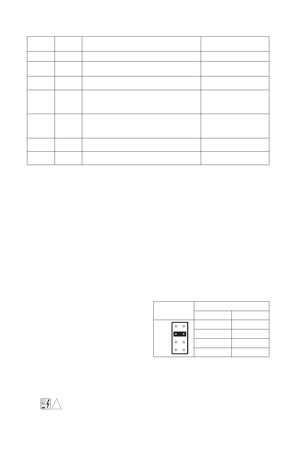
SETTING MOTOR CURRENT (Jumper J1)
Jumper J1 (on the Main Board) is used to
set the range of armature current which
can be further modified with the current
limit (CL) trimpot. The factory setting of J1
is 3.3 amps for 120 VAC controls and 2
amps for 240 VAC controls. The CL trimpot
is factory set to provide 150% of the J1 set-
ting. For example, when J1 is in the 10
amp position, the actual armature current
is 15 amps. When J1 is in the 5 amp posi-
tion, the control provides a maximum
armature current of 7.5 amps. The position of J1 should be set to the approximate DC motor
current rating. Table 4 is provided as a reference.
IV.
WIRING
WARNING! Read Safety Warning on page 2 before attempting to use this control.
Wire control in accordance with the National Electrical Code requirements and
other codes that apply. Be sure to fuse each conductor which is not at ground potential.
TABLE 3 – SELECTABLE JUMPER REFERENCE CHART
*NOTE: Location 1 Main Speed Control Board – Location 2 Relay Board (found on reversing models only).
TABLE 4 – JUMPER J1 SETTING vs
MOTOR HORSEPOWER
!
Jumper
Location*
Description
Factory Setting
J1
1
Establishes the range of maximum armature current
See section III, page 8
J2A, J2B
1
Sets the AC input line voltage (120 or 240 Volts AC) for
the main PC Board
Set according to model part
numbers. See table 1, Page 3
J3
1
Sets the DC output voltage range to motor (90V/180V)
Set according to model part
numbers. See table 1, Page 3
JR
1
Used to activate the return (RTN) circuit. “F” position –
RTN is jumpered to common.
“O” position – RTN used as a logic disable.
See section VI D, on page 11
Set to “F” position
JS
1
Used to set the STOP function operation. “NC” position –
Use a normally closed contact for open to stop operation.
“NO” position – Use a normally open contact for “close to
stop” operation.
Set to “NC” position
J1
2
Sets the operating AC line voltage for the
Relay Board (120 or 240 VAC)
Set according to model part
numbers. See table 1, Page 3
JW
1
Determines the priority of the Run and Stop logic com-
mands. See table 6, on page 12.
Set to “R” position for
“cycle on demand”
Jumper J1
Motor Horsepower Range
90 VDC
180 VDC
3.3A
2A
10A
5A
1/6
1/3
1/4 – 1/3
1/2 – 3/4
1/2
1
3/4 – 1
1
1
⁄
2
– 2