Jw s r – DE-STA-CO VARI-PAK DC CONTROL User Manual
Page 14
12
E. +24 VDC SUPPLY – The +24V terminal provides a nominal
1
24 VDC @ 12 mA output for
use with an external load such as one solid-state 3-wire proximity switch.
F. Common “COM” — This terminal is referenced to all logic signals (RUN, JOG, STOP)
through the Return (“RTN”) terminal. The control is factory supplied with jumper “JR” in
the “F” position which connects the “RTN” and “COM” terminals together.
Note: Control
will not operate unless jumper “JR” is in the “F” position.
VII. APPLICATION WIRING DIAGRAMS
Example 1: Solid-state switching devices, such as NPN transistors or proximity switches,
may be used for logic commands if they meet the following criteria:
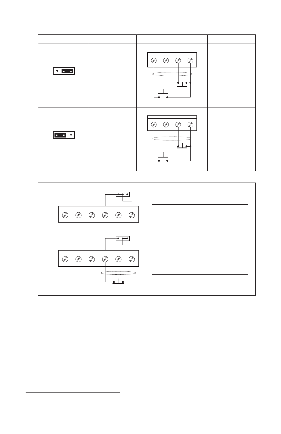
TABLE 6 – JUMPER “JW” OPERATION
*See section IV, items 1-4, on page 9.
COM
RTN
RTN
COM
OPEN TO
"F" "O"
"JR"
STOP
"JR"
*
"O"
"F"
FIGURE 11 – JUMPER “JR” OPERATION
Jumper “JR” in “F” position (factory setting)
connects “RTN” to “COM”
Jumper “JR” in “O” position opens the
“RTN” to “COM” circuit allowing the use of
an external disable contact. This will not
stop the indexer in run mode.
1
Output voltage provided can vary between 20 and 24 Volts DC.
Jumper “JW” Setting
Description
Circuit
Operation
JW
S
R
“Run” has priority
over “Stop.” Control
will run even if stop
contact is open. Use
this setting for “Cycle
on Demand” opera-
tion.
RUN
JOG
STP
RTN
STOP
START
*
When start contact is
made, control will
run with stop open.
If stop is closed and
then reopened, con-
trol will stop.
JW
S
R
“Stop” has priority
over “Run.” Control
will run only when
stop contact is
closed.
RUN
JOG
STP
RTN
STOP
*
START
When start contact is
made, stop contact
must be closed for
control to run.
Factory setting