DE-STA-CO VARI-PAK DC CONTROL User Manual
Page 12
1. Remote Potentiometer. Connect remote
potentiometer wires to terminals P1, P2
and P3, so that the “high” side of the
potentiometer connects to P3, the
“wiper” to P2 and the “low” side to P1.
(See figure 5.)
2. Analog Input. An
isolated 0-10VDC
analog voltage can also be used to drive
the control. Note: If an isolated signal
voltage is not available, an optional
signal isolator (Camco P/N
99A61455000000) should be used.
Connect the
isolated input voltage to
terminal P2 (positive) and P1 (negative).
(See figure 6.) Adjust the MIN trimpot
clockwise to achieve a 0+ output voltage.
V.
FUSING
AC Line Fusing – Most electrical codes require
that each ungrounded conductor contain fusing.
Separate branch circuit fusing or circuit breaker
may be required. Check
all electrical codes that
may apply to the installation. This control does
not contain AC line fuses. A 20 amp rated fuse
or circuit breaker can be used.
VI. LOGIC FUNCTIONS AND WIRING
Warning! Do not use any of the logic functions (STOP, RTN) as an emergency
stop since they are not fail-safe. Use only an AC line (L1, L2) disconnect for that
purpose. To prevent erratic operation, do not bundle logic wiring with AC line and
motor wires. Use shielded cables on logic wiring over 12” (30 cm) in length. See sec-
tion IV, items 1-4, on page 9.
The control contains several logic functions which are described in detail below. All connec-
tions are made to terminal block TB1. (See figures 2A and 2B, on pages 5 and 6, for TB1
location.)
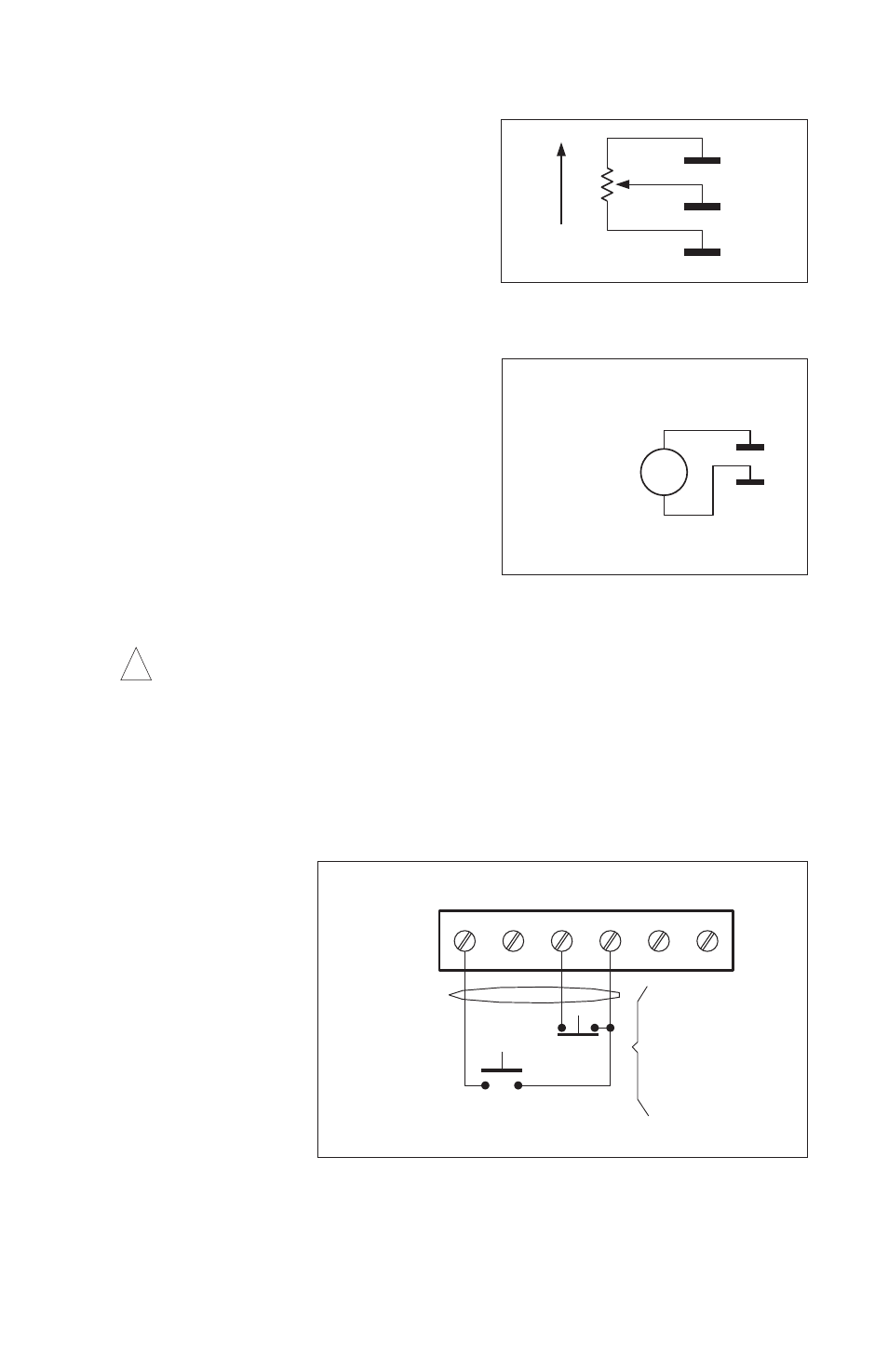
A. ”RUN” – Note:
This terminal is
sometimes
marked “START”
in older models.
A
momentary con-
tact closure
between terminals
“RUN” and “RTN”
latches the control
into a continuous
run mode. To stop
the control, the
stop circuit must be
activated by open-
ing the contact
between the
“STOP” and “RTN” terminals. Note: All momentary closures must be present for
no less than 50 milliseconds and a normally closed (NC) contact must be main-
tained between the “Stop” and “RTN” terminals in order for the drive to run.
10
P1
P2
P3
5K
FIGURE 5 – REMOTE POTENTIOMETER
CONNECTION
-
+
VDC
0-10
VOLTAGE SOURCE
USE AN ISOLATED
P2
P1
FIGURE 6 – ANALOG VOLTAGE
CONNECTION
Warning! Do not ground (earth)
P1 or P2 connection
!
RUN
JOG
STP
RTN
+24V COM
OPEN
TO STOP
CLOSE
TO START
A NORMALLY CLOSED
CONTACT MUST BE
INSTALLED BETWEEN
"RTN" AND "STOP" IN
ORDER FOR CONTROL
TO START, UNLESS
JUMPER "JW" IS IN THE
"R" POSITION.
TB1
See section IV,
items 1-4,
on page 9
FIGURE 7 – RUN COMMAND