Flow, Resilient seated butterfly valves – torques, Figure 1 - pressure distribution – Bray 31U User Manual
Page 4: More turbulence here, Case ii
Resilient Seated Butterfly Valves – Torques
All information herein is proprietary and confidential and may not be copied or reproduced without the expressed written consent of BRAY INTERNATIONAL, Inc.
The technical data herein is for general information only. Product suitability should be based solely upon customer’s detailed knowledge and experience with their application.
Introduction : 4
D. Seating/Unseating Torques (T
su
)
The seating/unseating torque value (T
su
) is a function of the
pressure differential, the seat material’s coefficient of friction,
the finished surface of the disc edge, the amount of interference
between the seat I.D. and disc O.D. when flanged in piping, the
seat thickness, and the type of service (media) for which the valve
is being used. In determining the T
su
values for Bray resilient
seated butterfly valves, Bray has developed Seating/Unseating
Torque Charts incorporating all bearing friction and stem seal
friction torques for three classes of services for both the valves
with standard discs (rated to full pressure) and for valves with
reduced diameter discs (rated for 50 psi [3.5 bar]). The three
service classes are:
Class I – Non-Corrosive, Lubricating Service
Class II – General Service
Class III – Severe Service
Please review the guidelines for each class in the technical
manual when determining which Seating/Unseating Torque Class
should be used. Most butterfly valves are used in Class II, General
Service applications.
E. Total Torque (T
T
)
The total torque values for Bray symmetrical disc valves for Case
I applications are shown in the Seating/Unseating Torque Charts
within this manual.
CASE II
(Disc in Partial To Full Opening Position)
T
T
= T
bf
+ T
ss
+ T
d
The total Torque for Case II using a symmetrical disc butterfly valve
is the summation of bearing friction torque, stem seal friction torque
and dynamic torque.
A. Bearing Friction Torque (T
bf
)
See Case I discussion. This torque value is normally included in
the Dynamic Torque Value.
B. Stem Seal Friction Torque (T
ss
)
See Case I discussion. This torque value is normally included in
the Dynamic torque value.
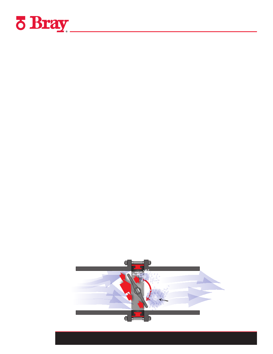
C. Dynamic Torque (T
d
)
In a symmetrical disc design, dynamic torque occurs between the
closed position, 0° and the full open position, 90°. With the disc in
the partially open position, velocity of the fluid passing the leading
disc edge is less than the velocity passing the trailing edge. This
variance in velocity past the leading disc edge and trailing disc
edge results in an unbalanced distribution of pressure forces on
the upstream side of the face of the disc. The total pressure forces
acting perpendicular to the disc face on the leading edge half of
the disc are greater than the total pressure acting perpendicular on
the trailing half of the disc. This uneven distribution of pressure on
the disc face (exists on both sides of the disc) results in a torsional
force which tries to turn the disc to the closed position (Figure 1).
This torsional closing force can become greater than the seating/
unseating torque value depending on the valve angle of opening
and differential pressure.
To determine dynamic torque, the following equation is applied:
T
d
= C
dt
d
3
∆P
Where:
T
d
= Dynamic Torque (lbs- in).
C
dt
= Coefficient of Dynamic Torque (based on disc shape
and angle of opening) (dimensionless)
d
= Diameter of Disc (Inches)
∆P = Pressure Differential Across Valve (psi)
FLOW
MORE
TURBULENCE
HERE
Clo
sin
g T
or
qu
e
Pr
essur
e F
or
ces
Figure 1 - Pressure Distribution