Bray 31U User Manual
Page 21
Resilient Seated Butterfly Valves – Flange Bolt Tensioning Data
All information herein is proprietary and confidential and may not be copied or reproduced without the expressed written consent of BRAY INTERNATIONAL, Inc.
The technical data herein is for general information only. Product suitability should be based solely upon customer’s detailed knowledge and experience with their application.
Mounting : 21
5. When all bolts are snug-tight, each bolt in the joint then
shall be tightened additionally by the applicable amount
of nut rotation given in Note 1. During tightening there
shall be no rotation of the valve or flange.
Note 1
For bolt lengths
not exceeding 8 diameters
or 8 inches (203.2 mm) =
1/4 turn
For bolt lengths
exceeding 8 diameters
or 8 inches (203.2 mm) =
1/2 turn
Disclaimer:
Bray Controls is issuing these recommendations only
as a guide to installation. This recommendation is
based on the full compliance of all materials supplied
to their appropriate specifications. Since many of the
components are not manufactured by Bray we can
take no responsibility for any damage caused during
installation.
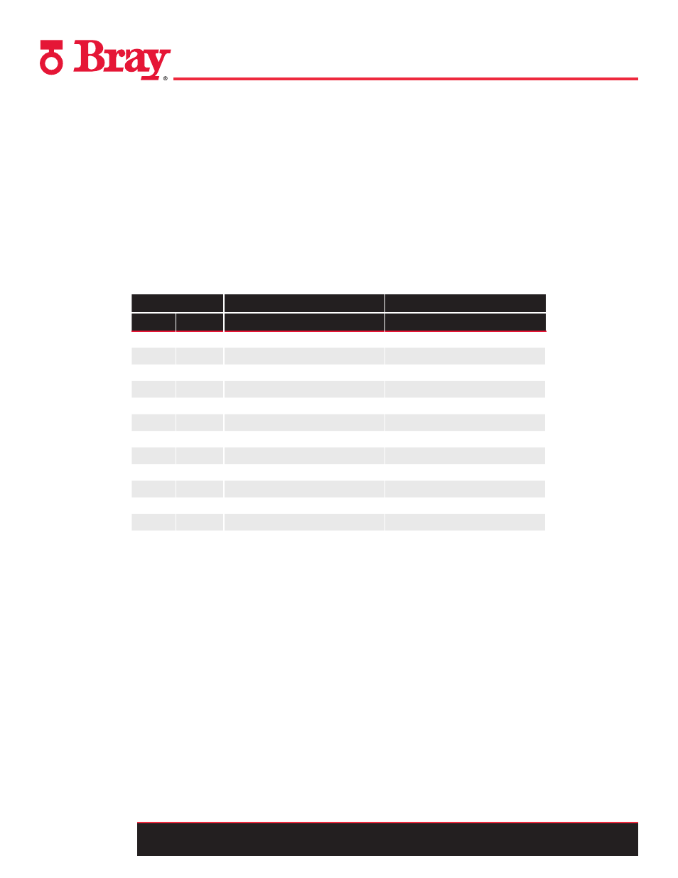
Series 20/21 and 30/31 - Flange Bolt Torque Chart
Valve Size
Normal Torque Range
Normal Torque Range
In
mm
Ft-lbs
N-m
2
50
30
40
2.5
65
30
40
3
80
35
50
4
100
35 - 40
50 - 55
5
125
35 - 45
50 - 60
6
150
35 - 50
50 - 65
8
200
45 - 55
60 - 75
10
250
55 - 75
75 - 100
12
300
65 - 110
90 - 150
14
350
75 - 120
100 - 165
16
400
75 - 120
100 - 165
18
450
85 - 130
115 - 175
20
500
85 - 130
115 - 175
Please note that the N-m and Ft-lbs values are based
on bolt size in respective metric and ANSI flanges, i.e.
these values are not a direct conversion between N-m
and Ft-lbs.
The values represent average torques needed to ensure
full compression of the resilient valves’ seats into the
valves’ bodies when installed in pipeline flanges. The
face of both flanges must come into full contact with
the valves’ metal bodies.
No additional torque is required for proper functioning
of the Bray resilient seated valves.
The torque values are based on using new, coarse-
threaded, lubricated fasteners. Up to 25% may be
added to the Normal Torque Range values when using
non-lubricated fasteners.
Torque Values specified by flange manufacturers
must
not be exceeded.