Bray 31U User Manual
Page 22
Resilient Seated Butterfly Valves – Flange Bolt Tensioning Data
All information herein is proprietary and confidential and may not be copied or reproduced without the expressed written consent of BRAY INTERNATIONAL, Inc.
The technical data herein is for general information only. Product suitability should be based solely upon customer’s detailed knowledge and experience with their application.
Mounting : 22
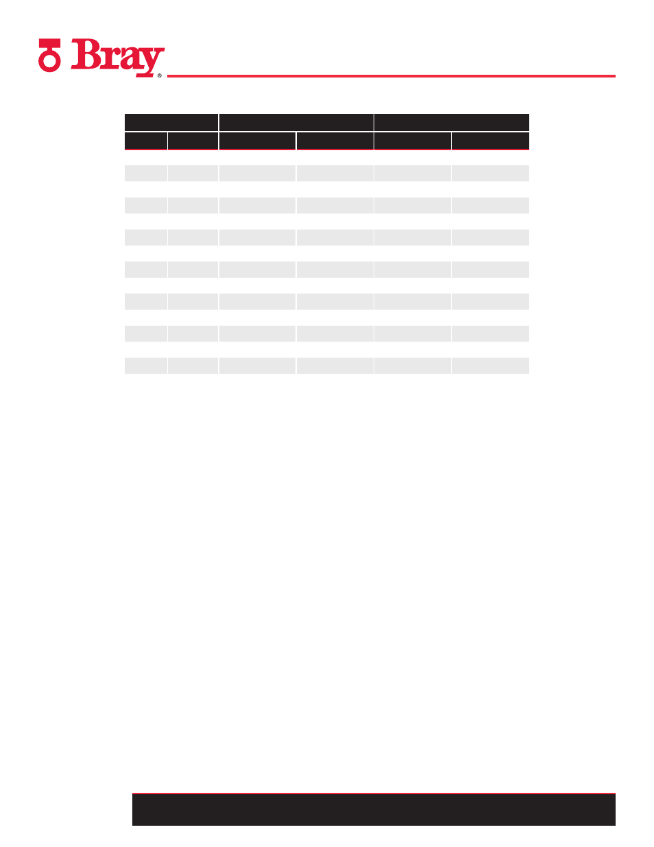
Series 22/23 Installation - Flange Bolt Torque Chart, 150 lb Flanges
Valve Size
Normal Torque Range
Max Torque Range
In
mm
Ft-lbs
N-m
Ft-lbs
N-m
2
50
30
40
35
50
2.5
65
30
40
35
50
3
80
35
50
40
55
4
100
35 - 40
50 - 55
40
55
5
125
35 - 45
50 - 60
50
65
6
150
35 - 50
50 - 65
65
90
8
200
45 - 55
60 - 75
80
110
10
250
55 - 75
75 - 100
100
135
12
300
65 - 110
90 - 150
120
165
14
350
75 - 120
100 - 165
140
190
16
400
75 - 120
100 - 165
140
190
18
450
85 - 130
115 - 175
170
230
20
500
85 - 130
115 - 175
180
245
24
600
100 - 150
135 - 205
220
300
The torque values are based on using new, coarse-
threaded, lubricated fasteners. Up to 15% may be
added to the Normal Torque Range values when using
non-lubricated fasteners. However, the maximum
torque should not be exceeded.
Flange gaskets are normally not used for installation
of S22/23 valves. Flange leakage may be caused by
combination of out-of-parallel and/or misaligned
flanges, and surface damage on the flange face and/or
the face of the valve seat. In such cases, suitable flange
gaskets may be used to control flange leakage.
Torque values specified by manufacturers of certain
flanges, for example plastic flanges, could be lower than
the values specified above. In such cases, the flange
manufacturers’ torque values must not be exceeded.
Use flange gaskets if necessary to secure flange seal.