3 motor connection for special motors, 4 delay time, 5 controls made by auma – AUMA Electric multi-turn actuators SA 07.1 - 48.1_SAR 07.1 - 30.1 NORM User Manual
Page 12: 6 heater, 7 motor protection, 8 remote position transmitter, Heater 12, Motor protection 12, Ptc thermistors 12, Thermoswitches 12
7.2
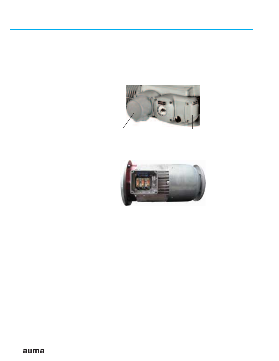
Motor connection for the sizes SA(R) 25.1/SAR 30.1 – SA 48.1.
From the size SA(R) 25.1, the power for the motor is connected to separate
terminals. For this, the cover at the motor connection compartment has to be
removed.
The control contacts are connected to the AUMA plug/socket connector.
Cross section motor terminals:
16 mm² to 70 mm² (6 to 2/0 AWG), depending on the actuator size
7.3
Motor connection for
special motors
For versions with special motors (e.g. DC motors), the connection is
performed directly at the motor (figure G-4).
7.4
Delay time
The delay time is the time from the tripping of the limit or torque switches to the
motor power being removed. To protect the valve and the actuator, we recommend
a delay time < 50 ms. Longer delay times are possible provided the output speed,
output drive type, valve type, and the type of installation are taken into
consideration.
We recommend to switch off the corresponding contactor directly by the limit or
torque switch.
7.5
Controls made by AUMA
In case the required reversing contactors are not to be installed in the control
cabinet, the controls AUMA MATIC or AUMATIC for the sizes SA(R) 07.1 – SA(R)
16.1 can be easily mounted to the actuator at a later date.
For enquiries and more information, please state our commission no. (refer to
actuator name plate).
7.6
Heater
AUMA multi-turn actuators have a heater installed as standard. To prevent
condensation, the heater must be connected.
7.7
Motor protection
In order to protect against overheating and extreme high temperatures at the
actuator, PTC thermistors or thermoswitches are embedded in the motor winding.
The thermoswitch is tripped as soon as the max. permissible winding temperature
has been reached.
Failure to integrate PTC thermistors or thermoswitches into the control circuit voids
the warranty for the motor.
7.8
Remote position transmitter
For the connection of remote position transmitters (potentiometer, RWG) shielded
cables must be used.
12
Multi-turn actuators SA 07.1 – SA 48.1 / SAR 07.1 – SAR 30.1
AUMA NORM
Operation instructions
Figure G-4: Connection special motor
Figure G-3: Connection to SA(R) 25.1
Cover motor connection compartment
AUMA plug/socket connector