All-purpose instrument – Atec Rohde-Schwarz-SMA100A User Manual
Page 6
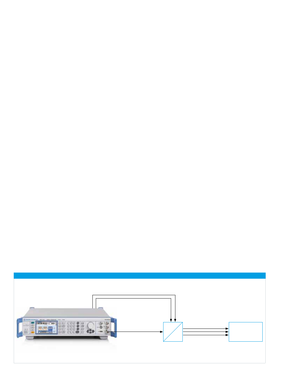
FFT analysis
A
D
Differential clock signal from the ¸SMA-B29 option
DUT
The ¸SMA100A signal generator
with the ¸SMA-B29 option
All-purpose
instrument
The signal generator has a lower frequency limit of 9 kHz,
which makes it suitable for use in EMC applications. The
upper frequency limit is 3 GHz or 6 GHz.
Amplitude and pulse modulation are provided as
standard; frequency and phase modulation with a
bandwidth of 10 MHz can be implemented optionally
(R&S®SMA-B20/R&S®SMA-B22).
The R&S®SMA-B22 enhanced phase noise performance
and FM/φM modulator option offers different setting
modes in which the user can optimally set the modulation
bandwidth and SSB phase noise.
These characteristics make the R&S®SMA100A suitable for
phase noise measurements on free-running VCOs, elimi-
nating the need for complex delay-line measurements.
Tests on integrated RF circuits frequently require a pure
clock signal in addition to the RF signal. In the past, an
extra signal generator was usually necessary in this case.
The R&S®SMA100A delivers a low-jitter clock signal
(R&S®SMA-B29 clock synthesizer option), which can be
set independently of the RF output signal. The clock signal
is available as a differential signal in the frequency range
from 100 kHz to 1.5 GHz at two separate connectors. It
enables, for example, A/D converter tests using only a
single signal generator.
The application note “Selecting a Signal Generator for
Testing A/D Converters” (1GP66) can be downloaded from
the Rohde & Schwarz website (Application Notes download
area).
Application example: A/D converter test with the R&S®SMA100A
6