Atec Rohde-Schwarz-SMA100A User Manual
Page 11
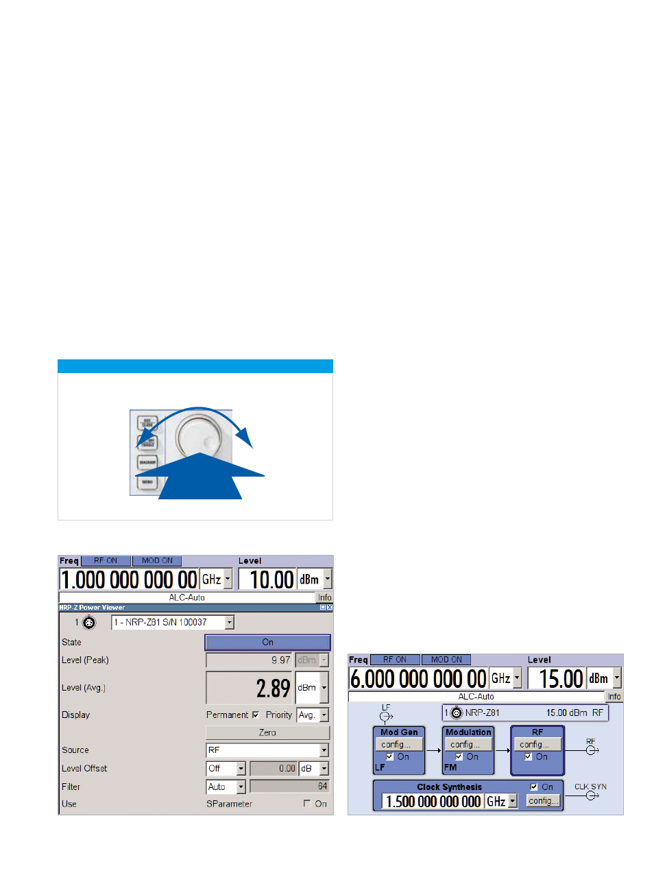
Turn
Click
Power measurement dialog on the R&S®SMA100A.
Block diagram of the R&S®SMA100A with power measurement display.
Rohde & Schwarz R&S®SMA100A Signal Generator 11
Intuitiveoperating
conceptand
versatileinterfaces
Intuitive operating concept
The signal flow is shown by a straightforward
block diagram on the R&S®SMA100A color display
(480 × 272 pixel ). Thus, the user can immediately see
the activated and deactivated generator blocks as well as
where settings can be made.
The entire operating manual for the R&S®SMA100A signal
generator is integrated into the instrument’s help system.
At the press of a button, the user can access details about
the function currently being used. For example, it is very
easy to display the associated remote-control command.
To make settings, the rotary knob, the cursor and function
keys or a USB mouse and/or keyboard can be used.
The above features combine to make operation of the
R&S®SMA100A easy and intuitive.
Connectors
The R&S®SMA100A can be remote-controlled via GPIB
or LAN and also manually operated from an external PC
using remote desktop control (VNC).
Two USB connectors on the front and the rear panel al-
low the use of USB devices such as a mouse or a memory
stick.
The R&S®NRP-Zxx USB power sensors can also be con-
nected directly to the R&S®SMA100A. The user can then
easily carry out highly precise power measurements in the
existing test setup without requiring an additional power
meter base unit.
Rotary knob for menu navigation