Specifications – Atec Rohde-Schwarz-SMP Series User Manual
Page 9
Microwave Signal Generator SMP
9
Specifications
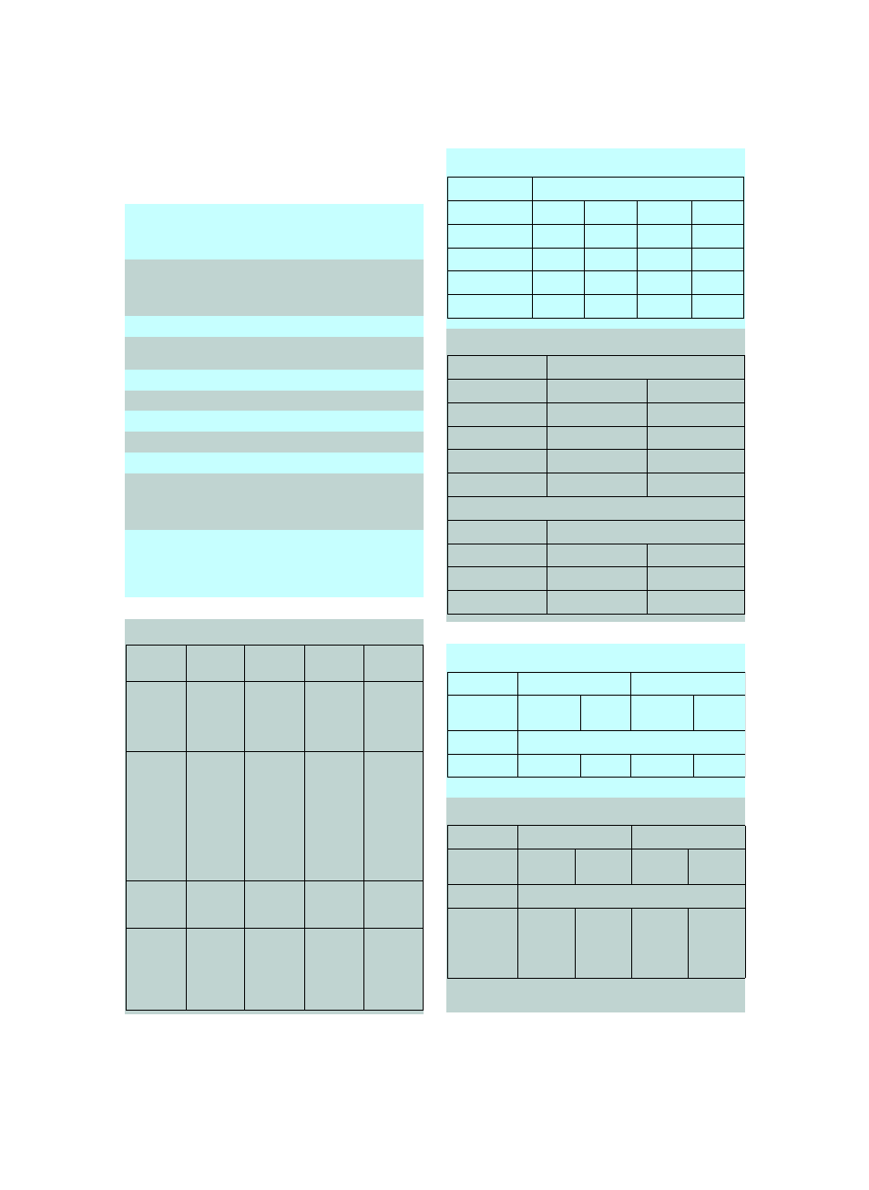
Frequency
Range (standard)
SMP02/SMP22
SMP03
SMP04
2 GHz to 20 GHz
2 GHz to 27 GHz
2 GHz to 40 GHz
Range (with option SMP-B11)
SMP02/SMP22
SMP03
SMP04
10 MHz to 20 GHz
10 MHz to 27 GHz
10 MHz to 40 GHz
Resolution
0.1 Hz
Setting time (to within <1x10
–6
) after
IEC-/IEEE-bus delimiter
<(11 ms + 5 ms/GHz)
1)
Phase offset
adjustable in 1° steps
Reference frequency
standard
option SMP-B1
Aging (after 30 days of operation)
1 x 10
–6
/year
<1 x 10
–7
/year
Temperature effect (0°C to 55°C)
2 x 10
–6
<1·10
–10
/°C
Warmup time
–
10 min
Output for internal reference
Frequency
Level V
rms
(EMF, sinewave)
Source impedance
10 MHz
1 V
50
Ω
Input for internal reference
Frequency
Permissible frequency drift
Input level (V
rms
)
Input impedance
1 MHz to 16 MHz in 1 MHz steps
3 x 10
–6
0.1 V to 2 V
200
Ω
Spectral purity
2)
Spurious
signals
SMP02
SMP22
SMP03
SMP04
Harmonics
2)
f <1.8 GHz
f
≥1.8 GHz
<–30 dBc
(<+8 dBm)
<–40 dBc
(<+10 dBm)
<–25 dBc
(<+8 dBm)
<–25 dBc
(<+15 dBm)
<–30 dBc
(<+3 dBm)
<–40 dBc
(<+3 dBm)
<–30 dBc
(<+0 dBm)
<–40 dBc
(<+0 dBm)
Harmonics
2)
(with options
SMP-B12/
-B13, pulse
modulation
on)
f <1.8 GHz
f
≥1.8 GHz
<–25 dBc
(<+8 dBm)
<–25 dBc
(<+11 dBm)
<–25 dBc
(<+8 dBm)
<–25 dBc
(<+11 dBm)
<–25 dBc
(<+3 dBm)
<–25 dBc
(<+3 dBm)
<–25 dBc
(<+0 dBm)
<–25 dBc
(<+0 dBm)
Subharmonics
f
≤20 GHz
f >20 GHz
–
–
–
–
–
<–40 dBc
–
<–30 dBc
Nonharmonics
at >10 kHz
from carrier
f <2 GHz
2 to 20 GHz
f >20 GHz
<–60 dBc typ.
<–60 dBc
–
<–60 dBc typ.
<–60 dBc
–
<–60 dBc typ.
<–60 dBc
<–54 dBc
<–60 dBc typ.
<–60 dBc
<–54 dBc
SSB phase noise, 1 Hz bandwidth, FM off
3)
Residual FM, rms, FM off
4)
Level
Maximum level
4)
SMP02/SMP22 (without options SMP-B12/-B13)
Maximum level
4)
SMP02/SMP22 (with options SMP-B12/-B13)
Offset from carrier
Frequency range
100 Hz
1 kHz
10 kHz
100 kHz
10 MHz to <2 GHz
3)
<–64 dBc
<–93 dBc
<–104 dBc
<–104 dBc
2 GHz to 10 GHz
<–64 dBc
<–93 dBc
<–105 dBc
<–105 dBc
>10 GHz to 20 GHz
<–58 dBc
<–87 dBc
<–99 dBc
<–99 dBc
>20 to 27/40 GHz
<–54 dBc
<–81 dBc
<–93 dBc
<–93 dBc
Weighting bandwidth
Frequency range
300 Hz to 3 kHz
30 Hz to 20 kHz
10 MHz to <2 GHz
3)
<5 Hz
<50 Hz
2 GHz to 10 GHz
<5 Hz
<50 Hz
>10 GHz to 20 GHz
<10 Hz
<75 Hz
>20 GHz to 27/40 GHz
<20 Hz
<150 Hz
Residual AM, rms, AM off
4)
Weighting bandwidth
Frequency range
300 Hz to 3 kHz
30 Hz to 20 kHz
10 MHz to <2 GHz
<0.1%
<0.2%
2 GHz to 20/27/40 GHz
<0.05%
<0.1%
SMP02
SMP22
Frequency range standard
with option
SMP-B15
standard
with option
SMP-B15
10MHz to <2GHz >+17 dBm
2 GHz to 20 GHz
>+11.5 dBm
>+10 dBm
>+20 dBm
>+18.5 dBm
SMP02
SMP22
Frequency range Pulse modu-
lation off
Pulse modu-
lation on
Pulse modu-
lation off
Pulse modu-
lation on
10MHz to <2GHz >+13 dBm
2 GHz to 20 GHz
like max. level
without
options
SMP-B12/
-B13
>+13 dBm
like max. level
without
options
SMP-B12/
-B13
>+13 dBm