Variety of applications, High-quality shielding, Frequency and phase modulation – Atec Rohde-Schwarz-SMP Series User Manual
Page 4: Pulse modulation
4
Microwave Signal Generator SMP
The SMP is setting standards with a reso-
lution of 0.1 Hz throughout its frequency
range, and even above 20 GHz.
Variety of applications
The SMP is ideal for the following appli-
cations:
◆
Substitution of local oscillators
◆
Measurements on nonlinear compo-
nents such as frequency multipliers or
high-level mixers
◆
Driving of TWTs and other power
stages
◆
Interconnection of several signal gen-
erators for intermodulation measure-
ments
◆
Tracking generator for spectrum and
network analyzers
High-quality shielding
Sensitivity measurements on low-noise
satellite receivers can only be made with
absolutely RF-leakage-proof signal
sources.
The comprehensive shielding of the SMP
ensures extremely low RF leakage.
Frequency and phase modulation
The SMP is fitted as standard with a
broadband FM modulator covering a
modulation frequency range up to 5 MHz
for deviations up to 10 MHz (20 MHz
above 20 GHz).
In addition, a precision FM/
ϕM modula-
tor (option SM-B5) with a modulation fre-
quency range of up to 1 MHz and maxi-
mum deviation of up to 1 MHz (2 MHz for
f >20 GHz) is available for testing commu-
nication receivers and for scientific appli-
cations.
FSK modulation
Thanks to a special frequency control cir-
cuit, the precision FM/
ϕM modulator fea-
tures an extremely high carrier frequency
accuracy and stability in the FM DC
mode. Digital frequency shift keying (FSK
modulation) is also possible. A deviation
of up to 1 MHz (2 MHz above 20 GHz) can
be selected.
Wide
ϕM modulation range
The wide frequency range of the phase
modulation extending from DC to 100 kHz
allows testing of phase-sensitive circuits.
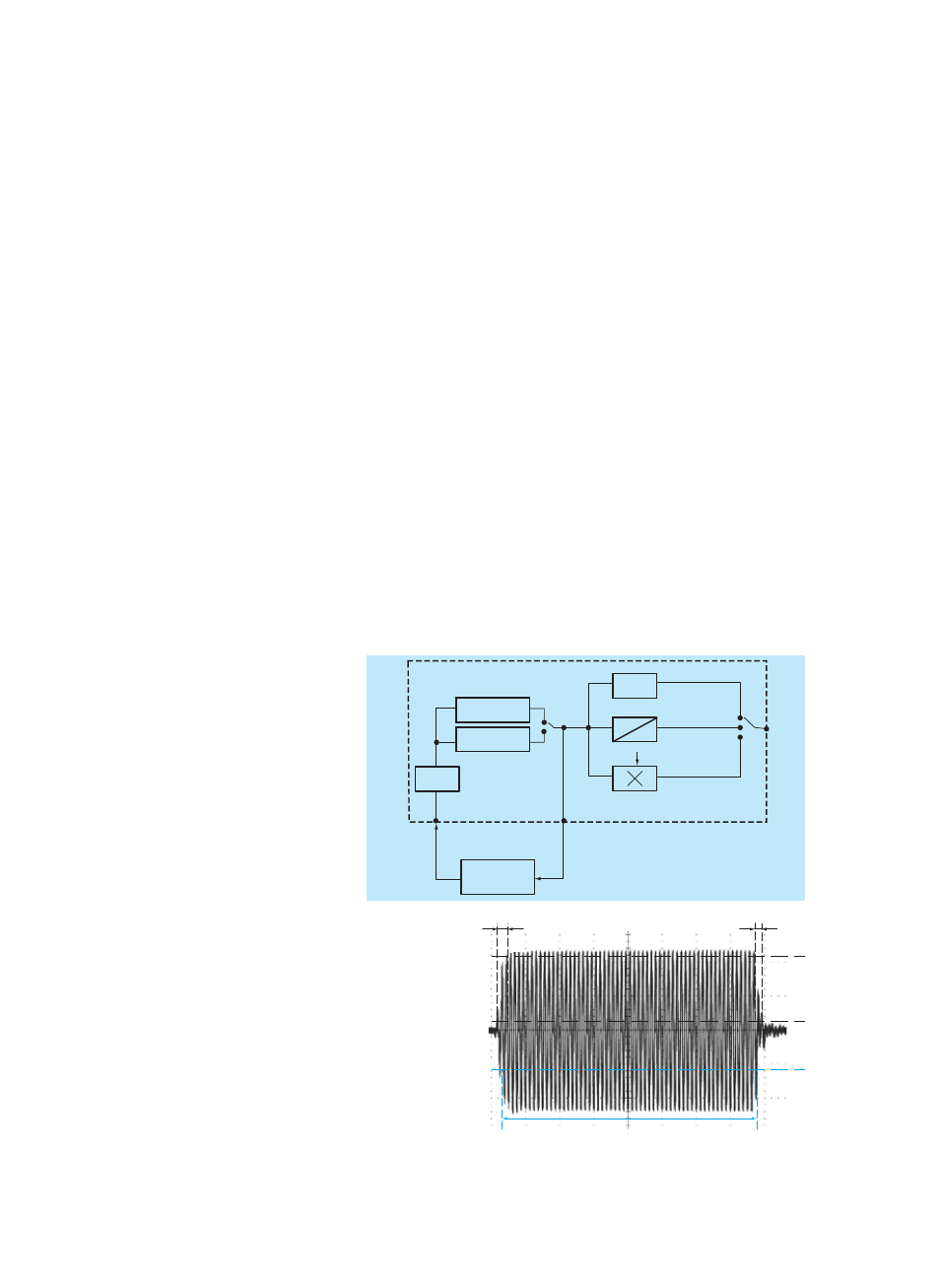
SMP for use as a VCO
In DC-coupled FM or
ϕM mode, the SMP
can also be used as a voltage-controlled
oscillator (VCO) and integrated into an
external frequency control loop. The RF
control output fitted on the rear panel is
very useful for this application.
The RF control output provides signals in
the frequency range 2 GHz to 20 GHz and
can for example be used for monitoring
the output frequency with the aid of a
frequency counter (FIG 3).
Pulse modulation
Ideal for radar receivers
All data specified for pulse modulation,
which is frequently used in the develop-
ment, production and maintenance of
radar receivers is valid throughout the
rated frequency range and also at the
important intermediate frequencies of
70 MHz and 140 MHz. The on/off ratio is
better than 80 dB, the rise/fall time
shorter than 10 ns. Pulse widths of less
than 20 ns are possible (FIG 4).
Optional pulse generator
In addition to feeding in external modula-
tion signals, the pulse generator (option
SMP-B14) can also be used to generate
FIG 3: SMP as VCO
YIG
2 GHz to 10 GHz
YIG
10 GHz to 20 GHz
direct
1
2
SMP 03/SMP 04
SMP-B11
6 GHz
2 GHz to 20 GHz
20 GHz to 40 GHz
10 M Hz to 2 GHz
RF
out
2 GHz to 20 GHz
(RF control output)
EXT1 or EXT2
SMP
FMDC non-synchronized
(unlocked)
FM/
ϕM
modulator
Frequency divider/
phase comparator/
control amplifier
DUT
FIG 4: Pulse modulator,
universally used in
microwave applications
such as radar;
(1) shortest pulse dura-
tion 20 ns,
(2) 3 ns typ. rise/fall
time, more than 80 dB
on/off ratio
(2)
(2)
90 %
10 %
50 %
(1)