Scalar network analysis – Atec Rohde-Schwarz-SMP Series User Manual
Page 6
6
Microwave Signal Generator SMP
5
5
5
5
5
5
3
3
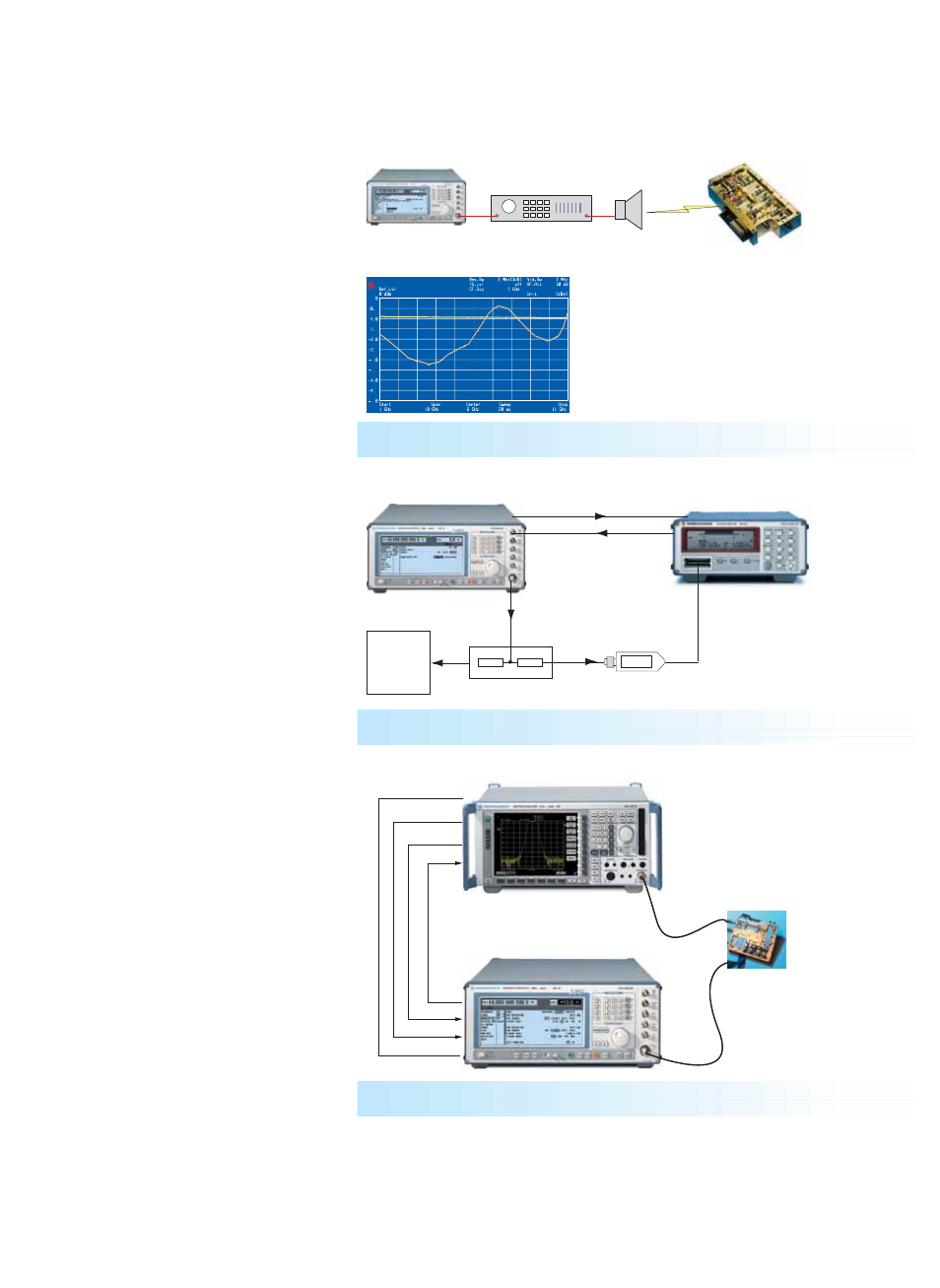
FIG 6: Output level with frequency response correction ON (yellow curve) and OFF (orange curve)
Power Amplifier
DUT
Horn Antenna
FIG 7: External level control for Signal Generator SMP
Power Sensor
NRV-Z15
DUT
DC
DC FREQ
RF
EXT ALC
Signal Generator SMP
V/GHz
Power splitter
Power Meter NRVS
Trigger
GPIB
REF 10 MHz
SMP
FSP + FSP-B10
Blanking signal
DUT
Blank
Aux
Aux
Trigger
FIG 8: Scalar network analysis with Signal Generator SMP and Spectrum Analyzer FSP with
option FSP-B10
User-defined correction of external
frequency responses
The user correction function is extremely
useful for fast RF sweeps, for example to
compensate nonlinearities of an ampli-
fier.
The known frequency response can be
compensated by entering level correction
values for up to 160 frequency points. The
correction values for the frequencies
between these points are determined by
means of automatic interpolation (FIG 6).
External level control using a power
meter
A very simple method is the external level
control with high level accuracy.
In this configuration, the SMP measures
automatically the level correction values
at a keystroke with the aid of an external
Power Meter NRVS or NRVD from
Rohde & Schwarz (FIG 7).
Scalar network analysis
The Signal Generator SMP used as a
tracking generator in conjunction with
the Spectrum Analyzer FSP and the
option FSP-B10 provides a unique scalar
network analysis function. This applica-
tion features an extremely wide dynamic
range, which allows, for example, filter
resonances in the stop band to be dis-
played at very low levels.
Due to the user-definable frequency off-
set, measurements on frequency-convert-
ing devices can also be performed with
this configuration.