Atec Picotest-G5100A User Manual
Page 8
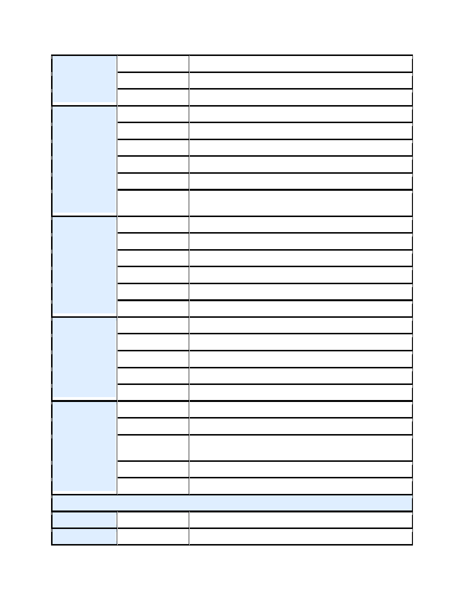
External
Modulation
Input
6
Voltage Range
±5V full scale
Input Resistance
8.7KΩ typical
Bandwidth
DC to 20KHz
SWEEP
Waveforms
Sine, Square, Ramp, Arb
Type
Linear or logarithmic
Direction
up or down
Sweep Time
1 ms ~ 500 Sec
Trigger
Internal , External or Manual
Marker
falling edge of sync signal
(programmable frequency)
BURST
7
Waveforms
Sine, Square, Ramp, Triangle, Noise, Arb
Type
Internal / external
Start/Stop Phase
-360º to +360º
Internal Period
1uS ~ 500Sec
Gated Source
External trigger
Trigger Source
Internal , External or Manual
Trigger Input
Level
TTL compatible
Slope
Rising or Falling (Selectable)
Pulse width
> 100 ns
Impedance
> 10KΩ, DC coupled
Latency
< 500 ns
Trigger
Output
Level
TTL compatible into
≥ 1 KΩ
Pulse width
> 400 ns
Output
Impedance
50 Ω typical
Maximum rate
1MHz
Fan-out
≤ 4 Picotest G5100As
Pattern Mode CHARACTERISTIC
Clock
Maximum rate
50MHz
Output
Level
TTL compatible into
≥ 2 KΩ
- Anritsu-PIM-MW82119A (2 pages)
- Boonton-PIM31 (6 pages)
- AWT-PIM-S1L-Tetra Series (2 pages)
- AWT-PIM-S1P Series (2 pages)
- AWT-PIM-S1L Series (2 pages)
- AWT-PIM-Expandable Series (2 pages)
- AWT-PIM-Single Series (2 pages)
- CCI-PimPro (4 pages)
- JDSU-FST-2310 (10 pages)
- JDSU-T-Berd-6000 (8 pages)
- Agilent-N9912A (2 pages)
- Agilent-E5515C (4 pages)
- Agilent-E4406A (20 pages)
- Agilent-N4010A (16 pages)
- Anritsu-S412E (19 pages)
- Anritsu-S810D-S820D (2 pages)
- Anritsu-S820E (16 pages)
- Anritsu-MT8221B (24 pages)
- Anritsu-MT8221B (28 pages)
- Anritsu-S412D (16 pages)
- Anritsu-MT8222A (8 pages)
- Anritsu-MT8220T (28 pages)
- Anritsu-MT8212E-MT8213E (32 pages)
- Anritsu-S332D-31D (12 pages)
- Anritsu-MT8212A (2 pages)
- Bird-SA Series (2 pages)
- Anritsu-S331E-S332E-S361E-S362E (16 pages)
- Anritsu-S331L (12 pages)
- Advantest-Q8163 (1 page)
- Agilent-83557A-83558A (4 pages)
- Agilent-8169A (6 pages)
- Agilent-11896A (5 pages)
- Agilent-81689A_B-81649A (6 pages)
- Agilent-8163A-81634A (8 pages)
- Agilent-81624B (11 pages)
- Agilent-81618A (112 pages)
- Agilent-8703A (16 pages)
- Agilent-8156A (8 pages)
- Advanced-Fiber-Solutions-OLK51 Series (5 pages)
- Anritsu_MS9720A (12 pages)
- Anritsu-ML9001A (4 pages)
- Corning-Optivisor400 (6 pages)
- Anritsu_CMA5000a (4 pages)
- Agilent-E6008B (12 pages)
- AFL-Noyes-FLX3 (6 pages)