Using kepco bop 1kw for solar device testing, Bop 1kw solar device testing features and benefits, Bop-gl 1000 watt model table – Atec Kepco-BOP-1 Series User Manual
Page 5
KEPCO, INC. • 131-38 Sanford Avenue • Flushing, NY 11355 USA • Tel: (718) 461-7000 • Fax: (718) 767-1102
Email: [email protected] • www.kepcopower.com
USING KEPCO BOP 1KW FOR SOLAR DEVICE TESTING
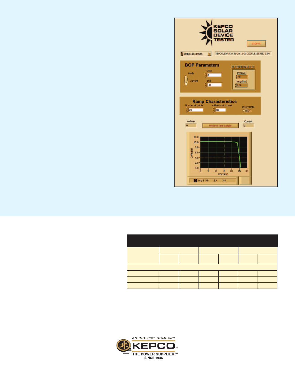
Demonstration Application Interface Showing User Inputs
and Rendered I-V Curve Output
The Kepco BOP 1KW provides a one-step solution for test and characterization
of solar cells and solar panels. A free LabView subvi allows rapid
characterization of the solar device using only the BOP 1KW, eliminating the
need for separate DVMs to measure voltage and current. The subvi is designed
for both I-V Trace and Dark I-V testing, and can be plugged in or easily adapted
to existing LabView test applications, even those previously using two DVMs.
This solution offers lower cost, greater throughput and increased ROI when
testing solar devices.
BOP 1KW SOLAR DEVICE TESTING FEATURES AND BENEFITS
• SOLAR DEVICE TESTING - Both I-V Trace and Dark I-V Tests supported.
• FLEXIBILITY - KEPCO BOP 1KW LabView Driver allows Solar Device testing while
maintaining full functionality of the BOP 1KW Instrument Power Supply features.
• FASTER THROUGHPUT - 20mS per point.
• ROI - Test setups are quick and easy, require no special programming for
synchronization, require no dedicated engineering resources to design and/or
maintain components comprising a custom solution.
• LOWER COST AND SIMPLICITY - No need to purchase, maintain and calibrate
two DVMs - Simplifies calibration, test setup and operation; no trigger
connections needed.
• RELIABILITY - With all triggering and measurements done within BOP 1KW
there are no synchronization or noise issues.
• PROVEN TECHNOLOGY - Enhancement of proven BOP 1KW technology.
• ENERGY CONSERVATION - Employs energy recuperation as well as active
Power Factor Correction (PFC).
NOTE: When connecting active loads, the steady-state voltage of the active load must not exceed
the maximum voltage rating of the BOP. Otherwise the overvoltage protection will shut down the
power supply.
For other volt-ampere combinations, consult factory.
1000 WATT
BOP 20-50GL
0 to ±20
0 to ±50
2.0
5.0
0.02%
0.01%
BOP 36-28GL
0 to ±36
0 to ±28
3.6
2.8
0.02%
0.01%
BOP 50-20GL
0 to ±50
0 to ±20
5.0
2.0
0.02%
0.01%
BOP-GL 1000 WATT MODEL TABLE
d-c OUTPUT RANGE
CLOSED LOOP GAIN
VOLTAGE
CHANNEL
Eo MAX
V d-c
Io MAX
A d-c
MODEL
CURRENT
CHANNEL
RIPPLE AND NOISE
VOLTAGE
rms
CURRENT
rms
The BOP-GL series models are a standard modification
of the 1KW that have been optimized for exceptionally
low current ripple and noise and improved stability
(drift and temperature), making them ideal for driving
inductive loads such as large magnets or motors.
These bipolar power supplies pass smoothly through
zero without switching to provide true ± voltage and
± current.
BOP 1KW GL SERIES
OPTIMIZED FOR VERY
LOW RIPPLE AND NOISE
5