Atec Kepco-BOP-1 Series User Manual
Page 4
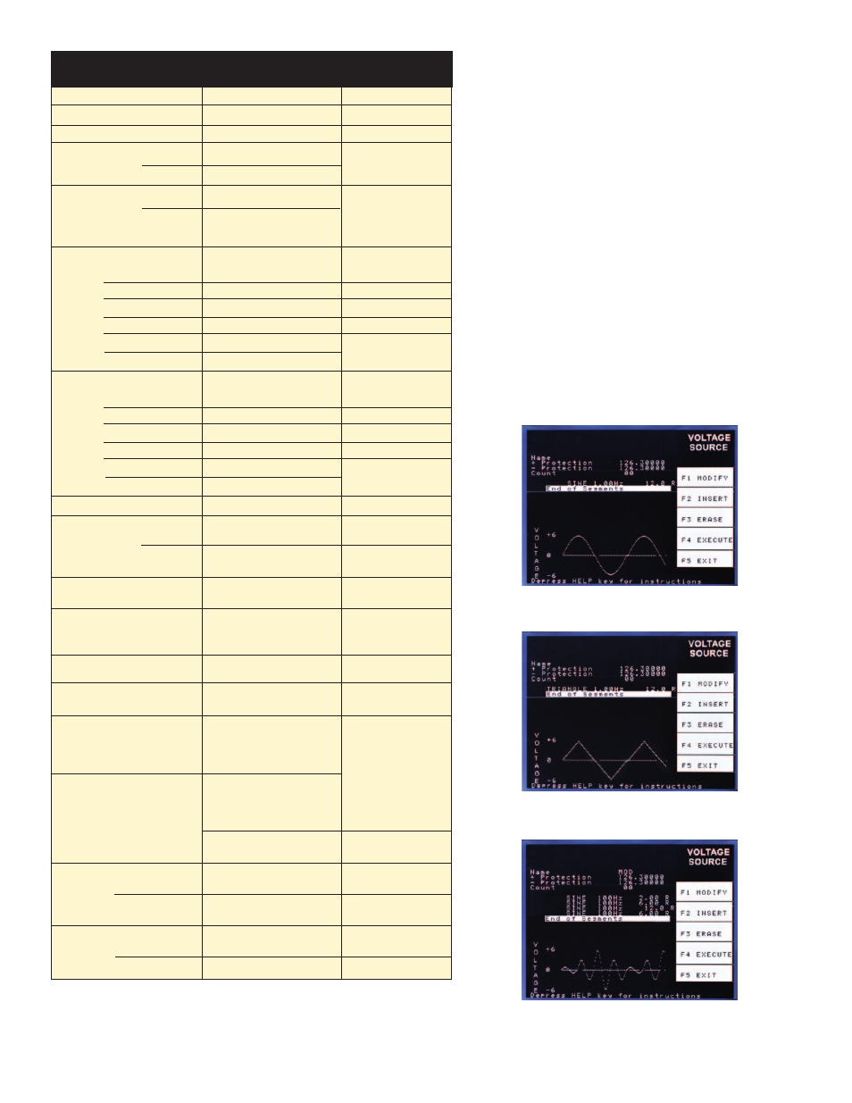
BOP 1KW ALLOW FOR AUTOMATIC
CREATION AND DISPLAY OF VARIOUS
WAVEFORMS AND COMPLEX PATTERNS
The 1000-watt models have an internal waveform generator
that allows a user to combine segments of a sinusoidal
waveform, triangular waveform, a ramp, a saw tooth
waveform and a square 50% duty cycle pulse, plus d-c to
create a variety of arbitrary waveforms. 3,933 of points per
basic waveform can be programmed with arbitrary phase
relationships. The resulting waveshape can be repeated
from 1 to 255 times. The waveshape can also be executed
indefinitely until a stop command is received. The wave-
shape graphics are displayed on the front panel-mounted
LCD display, which also shows both settings and actual d-c
output values. The programmed waveshapes can be used
to control either voltage or current with both positive and
negative values. It is possible to reproduce an a-c sinusoid
with differing degrees of distortion or dropouts for test
purposes. Alternatively, varying amounts of “noise” can be
added to a d-c output to gauge the effect on a test subject.
Sine Waveform
Triangle Waveform
Complex Sine Waveform
KEPCO, INC. • 131-38 Sanford Avenue • Flushing, NY 11355 USA • Tel: (718) 461-7000 • Fax: (718) 767-1102
Email: [email protected] • www.kepcopower.com
For full specs, visit our Web site at www.kepcopower.com/bophi.htm
BOP 1KW OUTPUT CHARACTERISTICS
SPECIFICATIONS
RATING/DESCRIPTION
CONDITION
Type of Stabilizer
Voltage/Current 4-quadrant
Switch mode
Output stage
Switching Frequency
Voltage Stabilization
in
Voltage
Mode
Source
Adjustment
Range
100KHz ±5%
-100% to +100% of rating
-100% to +100% of rating
0-50°C
voltage
current
Sink
Adjustment
Range
-100% to +100% of rating
-100% to +100% of rating
0-50°C,
recuperated energy is
sent back into line for
general reuse
voltage
current
0.05% of rating
0.1% of rating
0.02% of rating
0.02%/°C of rating
2% Eomax p-p
0.2% Eomax rms
min-max
input voltage
0-100% load current
0.5 - 8 hours
0-50°C
Includes switching
noise
source effect
load effect
time effect (drift)
temperature effect
ripple
noise
Current Stabilization
in
Current
Mode
0.05% of rating
0.2% of rating
0.02% of rating
0.02%/°C of rating
2% Iomax p-p
0.2% Iomax rms
min-max
input voltage
0-100% load current
0.5 - 8 hours
0-50°C
Includes switching
noise
source effect
load effect
time effect (drift)
temperature effect
ripple
noise
Error Sensing
0.25 volts per wire
Above rated output
Output Common
Mode Voltage
Series Operation
Output Protection Limiting
Output Stage
Protection
300V
Master/slave
Voltage and current
limited in four quadrants
Output overvoltage/
overcurrent,
heat sink overtemperature,
switchers overcurrent
Input Stage
Protection
(PFC)
Internal overvoltage,
undervoltage, overcurrent,
heat sink overtemperature,
fan inoperative
Triggers latched
shutdown protection
of the output module
and PFC stage.
Recover by cycling
power off, then on or
by pressing RESET
at the front panel
Maximum of
3 identical units,
up to 300V max.
Parallel Operation
Master/slave
Output to chassis
ground
Transient
Recovery in
Voltage Mode
5% of nominal output
nominal voltage,
50% load step
maximum
excursion
200 μsec
Return within 0.1%
of set voltage
recovery
time
Maximum of
5 identical units
Input circuit breaker
overcurrent
Trips circuit breaker to
shut off unit
Small
Signal
Bandwidth
2 KHz maximum
voltage channel
800 Hz maximum
(600 Hz Maximum)
(1)
current channel
Rise/Fall
Time
250/200 μsec
voltage channel
0.7/1.2 mSec
current channel
Into short circuit
Into nominal
resistive load
Into short circuit
Into nominal
resistive load
4
(1) BOP 6-125MG only.