What is a, Quadrant power supply, Bop 1kw (switch-mode) – Atec Kepco-BOP-1 Series User Manual
Page 2: Bop 1kw model table
Conventional d-c power supplies operate in
a single quadrant of the voltage-current
axis, delivering stabilized and adjustable
d-c voltage or current to a load. They may
be voltage stabilized, meaning that the
current varies with the load, or they may
be current stabilized, meaning that the
voltage varies with the load.
Kepco's BOP operate in all four quadrants
of the voltage-current axis, therefore their
output may swing seamlessly from negative
to positive voltage and the output current
may also swing from positive to negative
values. The result of this is that BOP will
function as a source or a sink, meaning it
will either deliver power to a load or absorb
power from a load. In order to do that, the
BOP is built as a power amplifier with a
bipolar output, having a frequency band-
width much larger than a regular power
supply. The frequency bandwidth is model
and option dependent.
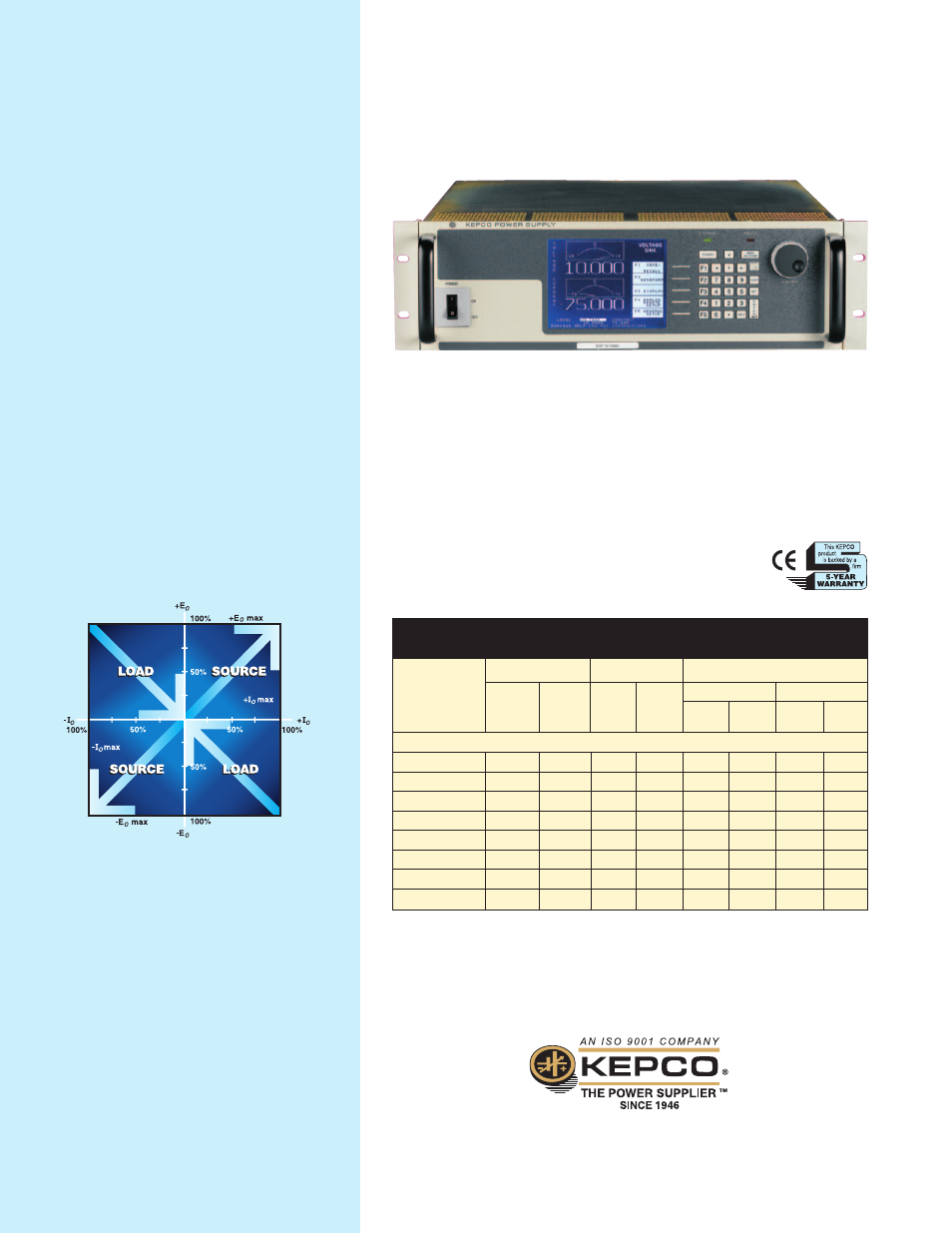
In quadrant 1 of the volt-ampere axis, both voltage
and current are positive so the BOP power supply
is able to deliver power to a load. In quadrant 3
both are negative and the BOP is also a source.
In quadrants 2 and 4, however, the voltage and
current are of opposite polarity. In these two
quadrants the BOP will act as a sink, absorbing
power. The sinking may be transient in
nature as BOP absorbs energy stored in
reactive elements or it may be steady
state, when for example, BOP controls
the discharge of a battery or acting as an
electronic load, constant current for an
external voltage source, or a constant
voltage for an external current source.
FOUR-QUADRANT OPERATION
FROM A KEPCO BOP POWER SUPPLY
+ CURRENT
LIMIT
– CURRENT
LIMIT
The BOP 1KW has two primary control channels: voltage or current. Either of these may
be controlled from full plus setting to full minus setting. To assure that they will
intersect in one of the two source quadrants to form a closed boundary as do
conventional unipolar power supplies, four auxiliary limit channels are provided:
plus voltage, minus voltage, plus current and minus current. These four are controllable
from a very small value to the nominal values. Their control does not pass through
zero as do the primary voltage and current channels. The intersection of whichever
primary control channel is engaged by the load and the respective limit channel does
form a closed boundary, and a variable load automatically crosses
over from the primary channel to the limit channel.
KEPCO, INC. • 131-38 Sanford Avenue • Flushing, NY 11355 USA
Tel: (718) 461-7000 • Fax: (718) 767-1102
Email: [email protected] • www.kepcopower.com
1000 WATT
BOP 6-125MG
0 to ±6
0 to ±125
0.6
12.5
0.05
1.5
24
1150
BOP 10-75MG
0 to ±10
0 to ±75
1.0
7.5
0.13
2.0
67
976
BOP 20-50MG
0 to ±20
0 to ±50
2.0
5.0
0.40
8.3
200
371
BOP 25-40MG
0 to ±25
0 to ±40
2.5
4.0
0.63
15.8
313
165
BOP 36-28MG
0 to ±36
0 to ±28
3.6
2.8
1.30
25
640
103
BOP 50-20MG
0 to ±50
0 to ±20
5.0
2.0
2.50
50
1250
55
BOP 72-14MG
0 to ±72
0 to ±14
7.2
1.4
5.14
104
2570
33
BOP 100-10MG 0 to ±100
0 to ±10
10.0
1.0
10.0
163
5000
16
BOP 1KW MODEL TABLE
NOTE: When connecting active loads, the steady-state voltage of the active load must not
exceed the maximum voltage rating of the BOP. Otherwise the overvoltage protection will shut
down the power supply.
d-c OUTPUT RANGE
CLOSED LOOP GAIN
VOLTAGE
CHANNEL
G V (V/V)
VOLTAGE
V d-c
CURRENT
A d-c
MODEL
CURRENT
CHANNEL
G I (A/V)
VOLTAGE MODE
SERIES R
mΩ
SERIES L
µH
SHUNT R
Ω
SHUNT C
µF
CURRENT MODE
OUTPUT IMPEDANCE
BOP 1KW (Switch-Mode)
Data subject to change without notice. © 2011 KEPCO, INC. Litho in USA
WHAT IS A
4
QUADRANT
POWER SUPPLY?
3
1
2
4
Using switch-mode technology for low dissipation when sinking power from
an active load, the BOP 1KW recuperate the energy for reuse. The key to this
is a bi-directional a-c input power factor correcting (PFC) circuit, which allows
transparent energy interchange without dissipative internal sinking.
2