Ts series iv specifi cations, 3u to 9u rack-mount power supplies – Atec Magna-Power_TSD Series User Manual
Page 4
www.magna-power.com
11
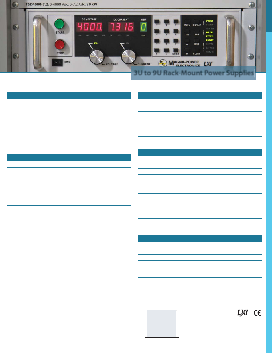
3U to 9U Rack-Mount Power Supplies
Input Specifi cations
Nominal Voltage
3 phase, 3 wire + ground
208 Vac, 3Φ (operating range 187 - 229 Vac)
240 Vac, 3Φ (operating range 216 - 264 Vac)
380 Vac, 3Φ (operating range 342 - 418 Vac)
415 Vac, 3Φ (operating range 373 - 456 Vac)
440 Vac, 3Φ (operating range 396 - 484 Vac)
480 Vac, 3Φ (operating range 432 - 528 Vac)
1 phase, 2 wire + ground
(5 kW Models Only)
208 Vac, 1Φ (operating range 187 - 229 Vac)
240 Vac, 1Φ (operating range 216 - 264 Vac)
Frequency
50 Hz - 400 Hz (operating range 45 - 440 Hz)
Power Factor
> 0.92 at maximum power for 3Φ units
> 0.70 at maximum power for 1Φ units
Output Specifi cations
Ripple
(See Model Charts)
Line Regulation
Voltage Mode: ± 0.004% of full scale
Current Mode: ± 0.02% of full scale
Load Regulation
Voltage Mode: ± 0.01% of full scale
Current Mode: ± 0.04% of full scale
Load Transient Response
2 ms to recover within ±1% of regulated output, with a
50% to 100% or 100% to 50% step load change
Effi
ciency
≥ 86% at full load (See Model Charts)
Stability
± 0.10% for 8 hrs. after 30 min. warmup
Isolation
User inputs and outputs: referenced to earth ground.
Maximum input voltage to ground: ±2500 Vac.
Maximum output voltage to ground:
±1000 Vdc for models less than or equal to 1000 Vdc
±(2000 Vdc + Vo/2) for models greater than 1000 Vdc or
with High Isolation Option (+ISO) where Vo is the unit’s
output voltage maximum
Maximum Slew Rate
Standard Models:
100 ms for output voltage change from 0 to 63%
100 ms for output current change from 0 to 63%
With High Slew Rate Option (+HS):
4 ms for output voltage change from 0 to 63%
8 ms for output current change from 0 to 63%
Bandwidth
Standard Models:
3 Hz for remote analog voltage programming
2 Hz for remote analog current programming
With High Slew Rate Option (+HS):
60 Hz for remote analog voltage programming
45 Hz for remote analog current programming
Control Specifi cations
Voltage Programming Accuracy
± 0.075% of full scale voltage
OVT Programming Accuracy
± 0.075% of full scale voltage
Current Programming Accuracy
± 0.075% of full scale current
OCT Programming Accuracy
± 0.075% of full scale current
Voltage Readback Accuracy
± 0.2% of full scale voltage
Current Readback Accuracy
± 0.2% of full scale current
External Analog Programming and
Monitoring Levels
0 - 10 Vdc
External Analog Output Impedances
Voltage output monitoring: 100 Ω
Current output monitoring: 100 Ω
+10 Vdc reference: 1 Ω
External Digital Programming and
Monitoring Limits
Input: 0 to 5 Vdc, 10 kΩ input inpedance
Output: 0 to 5 Vdc, 5 mA drive capacity
Remote Sense Limits
3% maximum voltage drop from output to load
Environmental Specifi cations
Ambient Operating Temperature
0 °C to 50 °C
Storage Temperature
-25 °C to 85 °C
Humidity
Relative humidity up to 95% non-condensing
Temperature Coeffi
cient
0.04 % / °C of maximum output voltage
0.06 % / °C of maximum output current
Air Flow
Side air inlet, rear exhaust
Water Cooling (+WC Option)
(Diagrams Available)
Inlet temperature: 25°C
Flow rate (minimum): 1.5 GPM for 15 kW units
3.0 GPM for 20 to 30 kW units
4.5 GPM for 45 kW units
80 PSI maximum pressure
Physical Specifi cations
Power
Size (H” x W” x D”)
Rack Units
Weight
5 kW
5.25 x 19 x 24 in (13.3 x 48.3 x 61.0 cm)
3U
74 lbs (33.60 kg)
10 kW
5.25 x 19 x 24 in (13.3 x 48.3 x 61.0 cm)
3U
94 lbs (42.64 kg)
15 kW
5.25 x 19 x 24 in (13.3 x 48.3 x 61.0 cm)
3U
114 lbs (51.71 kg)
20 kW
10.25 x 19 x 24 in (26.0 x 48.3 x 61.0 cm)
6U
197 lbs (89.36 kg)
25 kW
10.25 x 19 x 24 in (26.0 x 48.3 x 61.0 cm)
6U
217 lbs (98.43 kg)
30 kW
10.25 x 19 x 24 in (26.0 x 48.3 x 61.0 cm)
6U
237 lbs (107.50 kg)
45 kW
15.75 x 19 x 24 in (40.0 x 48.3 x 61.0 cm)
9U
349 lbs (158.30 kg)
TS Series IV Specifi cations
Note: Specifi cations are subject to change without notice. For three-phase confi gurations,
input specifi cations are line-to-line. Unless otherwise noted, input voltages and cur-
rents are specifi ed for three-phase confi gurations.
Output Current (Adc)
Output V
oltage
(V
dc)
(Voltage Maximum, Current Maximum)
Output Operation Region