Battery simulator battery/charger simulators, Fa st tra nsi en t r espo ns e pow er su pp lie s – Atec Keithley-2302-2306D User Manual
Page 3
www.keithley.com
1.888.KEITHLEY
(U.S. only)
S
p
E
c
Ia
L
Iz
E
d
p
O
W
E
R
S
U
p
p
L
IE
S
A G R E A T E R M E A S U R E O F C O N F I D E N C E
Fa
st
tra
nsi
en
t r
espo
ns
e
pow
er
su
pp
lie
s
Measure Long-period Waveform currents
For pulse trains with periods longer than 850ms, the Models 2302 and
2306 offer a unique, long integration current measurement mode. This
mode can provide an average measurement of a current waveform from
850ms up to 60 seconds long.
Measure Low currents accurately
The Models 2302 and 2306 are based on Keithley’s expertise in low current
measurement technologies, so they’re well-suited for making fast, accurate
measurements of sleep and standby mode currents. With 100nA resolution
and 0.2% basic accuracy, they provide the precision needed to monitor the
low sleep mode currents of both today’s battery-operated products and
tomorrow’s.
Verify Load currents in all Operating States
The Models 2302 and 2306 employ a unique pulse current step function
for measuring the load current at each level of a device’s operational
states. (See Figure 4.) For example, if a cellular phone is ramped up and
down through as many as 20 discrete power consumption states, the
Models 2302 and 2306 can measure the load currents in synchronization
with the current steps. This capability allows a test engineer to verify
performance at each operational state and simultaneously acquire power
consumption information. The fast current measure capability is another
way the Models 2302 and 2306 power supplies save test time and produc-
tion costs.
i
1
i
2
i
3
i
4
i
5
i
6
i
7
i
8
Trigger levels
load currents
Figure 4. These power supplies can obtain a load current profile
synchronized to the transitions of a dUT as it is stepped through its
operating states.
Simulate a discharged Battery for charger Testing
The Models 2302 and 2306 can sink up to 3A continuously, just like
an electronic load. This allows these supplies to simulate a discharged
rechargeable battery for use in testing the performance of battery chargers
or battery charger control circuitry.
The Model 2306 Battery/Charger Simulator combines the functionality of
both the charging current source (the charger channel) and the current
sinking to simulate the recharging of a discharged battery (the battery
channel) in a single enclosure. (See Figure 5.)
Open-Sense Lead detection
The Model 2302 and 2306 have an automatic open–sense lead detection
capability, which indicates if there is a broken remote sense lead or an
open connection from a remote sense lead to the test fixture. To ensure
the output voltage does not change from the programmed level, which
could cause production devices to be improperly calibrated, the user can
set high and low limits around the desired voltage level.
Independent digital Voltmeter Inputs
Many programmable power supplies offer output readback capabilities, but
the Model 2302 and 2306 also offer DVM inputs. Both instruments allow
measuring signals from –5V to +30V DC anywhere in the test system with
the same rated accuracy as the voltage readback. The Model 2306 has two
sets of DVM inputs; the Model 2302 has one. The DVMs and the power
sources can operate simultaneously. For many applications, these built-in
DVMs eliminate the expense and space required to add a separate voltage
measurement instrument.
r
+
–
Battery channel
charger channel
V
battery
V
charger
> V
battery
Battery
Terminals
charger
Terminals
+
–
i
i
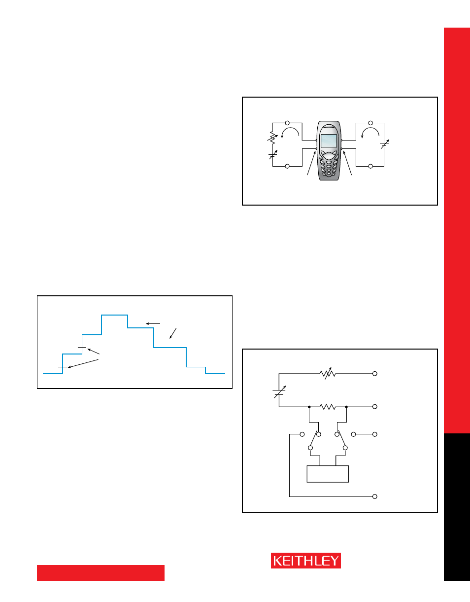
Figure 5. For charger control circuit testing applications, the Model
2306 and 2306-pJ can provide the functions of both a charger-simulat-
ing source and a discharged battery simulator.
Figure 6. Model 2302 and Model 2306 Battery channel Block diagram.
The Model 2306 charger channel is identical except it does not have
the variable output resistance.
DVM
+
–
+
–
V
OuT
V
in
–5V to +30V Dc
r
i
Sense
r
OuT
+
–
2302
2306, 2306-pJ
Battery Simulator
Battery/Charger Simulators