Phenix, Radio interference voltage (riv) testing, Model riv-3 – Atec Phenix-PD2U User Manual
Page 6
www.phenixtech.com
TECHNOLOGIES
PHENIX
R
raDio interference Voltage
(riV) testing
The RIV meter is an instrument for the measurement of Radio
Influence Voltage according to NEMA 107-1987 and other
relevant standards (ANSI 63-2-1996, VDE 876, DIN EN 55016-1-1).
The instrument has a bandwidth of 9 kHz and a tunable
center frequency of 10 kHz-10 MHz. Technically, the RIV
meter is a selective µV-meter. However, the meter reading is
weighted according to the CISPRE weighing curve, whereas
the repetition rate has a strong impact on the reading. The
RIV meter is an ideal instrument to replace outdated RIV
measurement instruments in transformer testing labs.
Some routine PD measurements are still done according to
IEEE standards requiring the measurement of RIV. The RIV value
is given in µV (interference voltage). A narrow band filter performs
a quasi-integration of the PD pulses with a quasi-peak detection
at the center frequency. This center frequency can be adjusted
between 10 kHz and10 MHz.
Two factors determine the RIV in µV: the transferred charge and the
repetitive rate of the PD impulse (number of PD pulses per second).
Because of this proceeding, a direct translation of the measured RIV
values (µV) into values of apparent charge in pC is not possible.
Historically, the RIV technique is based on measurement receivers to
estimate the disturbance of communication lines. Thus, properties of
those instruments then available became part of the NEMA standards.
However, both the 9 kHz bandwidth and the CISPRE weighing curve
put emphasis on some partial discharge activity while they tend hiding
others.
The calibration of the RIV measurement is done using an RIV calibrator,
injecting a sine wave of typically 100 µV into the bushing. The multiplexer
of the RIV meter is used to conveniently determine the correction fac-
tor according to NEMA 107-1987 and other standards. Here, the unit
compares the voltage injected (loaded by the bushing’s impedance),
with the voltage detected at the bushing tap to automatically determine
the k-factor. This correction factor is then stored independently for each
channel during calibration. The standard calibrator for RIV calibration,
CAL3A, offers a selectable frequency range of 600-1350 kHz in steps of
50 kHz. The output voltage covers 10 µV to 10 mV in 1-2-5 steps.
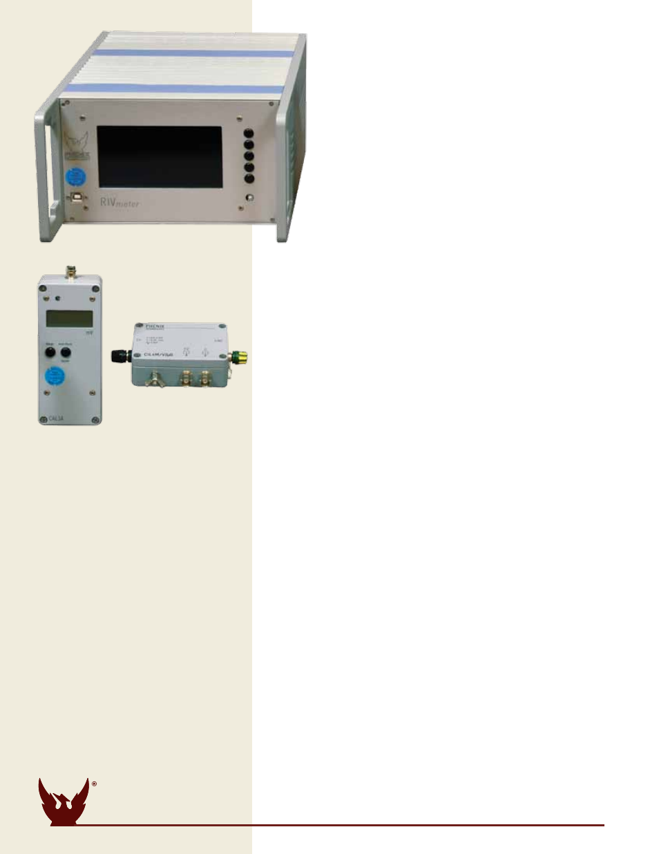
calibrator
Model cal3a
•
Selectable level 10 µV (20dBµV) to 10 mV (80 dBµV)
•
Available in steps of 1-2-5
•
Error rate of +/- 5%
•
Adjustable Frequency between 600kHz & 1350kHz (50kHz steps)
•
Comes with ISO17025 Calibration Certificate traceable to DKD
3 channel Multiplexer
Model MuX3
•
Built in multiplexer with three inputs for PD measurement and
three inputs for voltage measurement
•
Firmware offers individual setups and calibration factors
•
Second line of push buttons for direct channel selection
note:
Multiple channel RIV systems require a coupling capacitor
per channel. For a Coupling Capacitor to operate in the range of 50 to
500 Hz, it requires the next higher rated voltage capacitor.
MoDel riV-3
coMPonents
Desktop acquisition and
Display unit (three channel)
•
Backlit LCD Display
•
Meter display 0-2500 µV (@ k=1)
•
Auto-range function
•
Automatic storage of current
settings
•
RIV bandwidth 9kHz
(ANSI C63.3-1996)
•
Reference channel for RIV
calibration
•
Center Frequency 100 kHz – 2MHz
(10 kHz steps)
•
Serial Interface (USB, 57.6 Bit/s fixed)