Technical specifications-atm – Atec JDSU-ANT-5 User Manual
Page 8
8
ANT-5 SDH ACCESS TESTER
ATM (Option) 4565/93.54
For testing of ATM services carried over PDH, SDH, and SONET
– Tests ATM over DS1, E1, E3, DS3, E4,VC-4/0C-12 and VC4c/
0C-12c, STS-1 SPE
Operating Modes
– Terminated Mode
– In-line Monitor Mode
– Intrusive Thru Mode (E1 only)
ATM Interfaces
Signal structures for all bit rates
– Unframed test pattern
– Framed test pattern
Frame types
– 1544 Kbps unframed/framed (SF, ESF)
– 2048 Kbps unframed/framed G.704 CAS, 30/31 channels
with/without CRC
– 34368 Kbps unframed/framed G.751, G.832
– 44736 Kbps unframed/framed C-parity, M13
– 139264 Kbps unframed/framed G.751
ATM Layer Traffic Generation
Traffic generation
1 foreground, 1 background channel
Interface
UNI/NNI according to 1.361
Payload scrambling
Enable/Disable
Rate adaption by stuffing
Idle/Unassigned
Traffic profile
Traffic selection
Cell(s), %
Type
CBR,VBR (specifying PCR, SCR)
ATM test cells
Full cell header editing including:
VPI
0 to 255
VC I
0 to 65535
GFC
0 to 15
CI
ON/OFF
CLP
0/1
Payload type foreground channel:
– AAL-0 filled with test pattern
– O.191 test cell format (1995, 1997)
ATM Layer Traffic Analysis
ATM cell analysis
Analysis of ATM cells according to OAM cell analysis for VC/VP
AIS and RDI
Filter function for:
VPI
0 to 255
VCI
0 to 65535
CLP
0/1
ATM link and channel statistics
Counts on link parameters:
Total, Load, Idle/Unassigned, CLP = 1, OAM
Counts on ATM channel/path under test (filtered VCI,VPI):
Total, CLP = 1, OAM
O.191 QoS measurements
Reported anomalies:
Cell Loss, Cell Error, Cell Mis-insertion
Reported delay results:
Min CTD, Max CTD, Mean CTD, 2-pt CDVpp
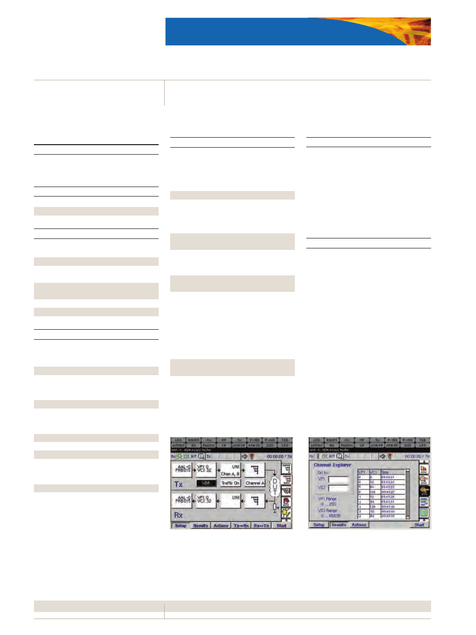
ATM Channel Explorer
Automatic detection of active VCI/VPIs with the user-defined
range.
The results are listed in tabular form.
Test patterns
Test patterns may be generated and measured for any of the
provided bit rates either directly at the ATM interface or within
the STM-16/STM-4/STM-1 substructure.
PRBS: 2
11
-1, 2
15
-1, 2
20
-1, 2
23
-1, 2
31
-1, 2
11
-1 inv, 2
15
-1 inv, 2
20
-1 inv,
2
23
-1 inv, 2
31
-1 inv
User programmable word
16 bits
ATM Anomaly and Defect Insertion
ATM anomaly generation
Single injection
ATM anomaly types
The following anomalies can be generated:
HUNC, HCOR, Cell Error, Cell Loss
ATM defect generation
Static
ON/OFF
ATM defect types
The following defects can be injected:
VC-AIS,VC-RDI,VP-AIS,VP-RDI
ATM Anomaly and Defect Detection
ATM LED indicators
The following status LEDs at the top part of the display will
directly reflect the most critical ATM alarms/defects:
ATM VP, ATM VC, LCD, LSS
ATM anomaly detection
The following anomalies will be detected and shown with the
results pages (Anomaly Count, Graphs, Event Log):
HUNC, HCOR
ATM defect detection
The following ATM defects will be detected and listed either in
tabular form with the defect panel or graphical form with the
Graph (defects) page:
LCD, CTM,VC-AIS,VC-RDI,VP-AIS,VP-RDI
Technical
Specifications-ATM
Figure 9: ATM signal structure
Figure 10: ATM Channel Explorer