Specifications – Atec Anritsu-MP1763C-64C-64D User Manual
Page 6
6
•
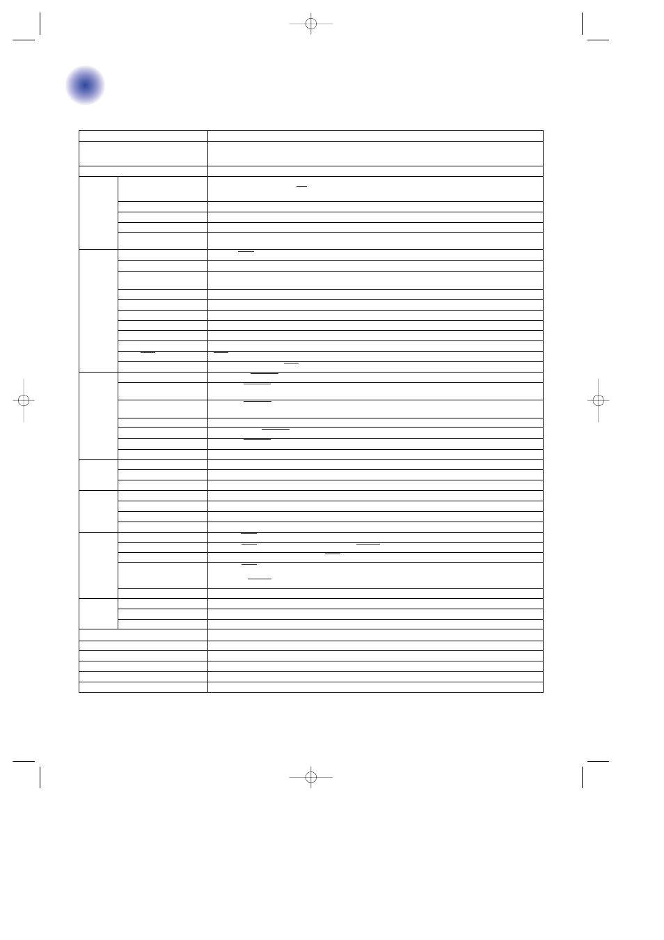
MP1763C Pulse Pattern Generator
Operation frequency
0.05 to 12.5 GHz
Frequency range: 0.05 to 12.5 GHz
Internal CLOCK (Option 01)
SSB phase noise:
≤
–85 dBc/Hz (0.05 to 4 GHz),
≤
–80 dBc/Hz (4 to 8 GHz),
≤
–75 dBc/Hz (8 to 10 GHz),
≤
–70 dBc/Hz (10 to 12.5 GHz)
∗
At 10 kHz offset, 1 Hz bandwidth
External CLOCK input level
0.4 to 2.5 Vp-p
Pseudorandom binary
Pattern: 2
n
– 1 (n: 7, 9, 11, 15, 20, 23, 31)
sequence pattern (PRBS)
Mark ratio: 1/2, 1/4, 1/8, 0/8 (1/2, 3/4, 7/8, 8/8 are possible with logic inversion)
Bit shifts number for mark ratio varied: 1, 3 bits selectable
DATA pattern
DATA length: 2 to 8388608 bits
Pattern
Alternate pattern
A/B pattern DATA length: 128 to 4194304 bits (128 bit steps); Loop time: A, B pattern (1 to 127, 1 steps)
Zero substitution pattern
Zero bit length: 1 to (pattern length – 1) bits; Pattern: 2
n
(n: 7, 9, 11, 15)
Error rate: 10
–n
(n: 4, 5, 6, 7, 8, 9), and single error
Error addition
External error injection: Provided
Number of outputs
2 (DATA/DATA independently)
Amplitude
0.25 to 2 Vp-p, 2 mV steps
V
OH
: –2 to +2 V, 1 mV steps
Offset voltage
Display: V
OH
, V
TH
or V
OL
selectable
Rise/fall time
Typical 30 ps (10% to 90% of amplitude)
DATA
Pattern jitter
≤
20 psp-p, typical 10 psp-p
output
Waveform distortion (0-peak)
≤
15% or
≤
150 mV whichever is greater
Gating input
Provided
Load impedance
50
Ω
(with back termination)
Connector
APC-3.5
DATA/DATA tracking
DATA amplitude and offset voltage can be set to the same values as for DATA.
Cross point adjustment function
The cross point of DATA/DATA outputs can be adjusted at semifixed resistor of side.
Number of outputs
3 (CLOCK 1/CLOCK 1, CLOCK 2)
Amplitude
CLOCK 1/CLOCK 1: 0.25 to 2 Vp-p (2 mV steps)
CLOCK 2: 1 Vp-p
CLOCK
CLOCK 1/CLOCK 1: V
OH
–2 to +2 V (1 mV steps)
output
Offset voltage
CLOCK 2: V
OH
0 V fixed
Rise/fall time
Typical 30 ps (10% to 90% of amplitude)
Load impedance
50
Ω
(CLOCK 1/CLOCK 1: with back termination)
Connector
CLOCK 1/CLOCK 1: APC-3.5, CLOCK 2: SMA
Delay
±500 ps (1 ps steps)
Number of outputs
DATA 8, CLOCK 1
Output level
ECL
Connector
SMA
Number of outputs
DATA: 4, CLOCK: 1
Amplitude
0.5 to 2 Vp-p (2 mV steps)
Offset voltage
V
OH
: –1.5 to +1.5 V (1 mV steps)
Connector
SMA
Operation bit rate
1/4 DATA/DATA: 100 Mbit/s to 3.125 Gbit/s
Number of outputs
1/4 DATA/DATA differential 4 system. 1/4 CLOCK/CLOCK differential 1 system
Amplitude
0.5 to 2.0 Vp-p (2 mV steps), 1/4 DATA/DATA: All channels same settings
1/4 DATA/DATA: –1.0 to +2.5 V (V
OH
) (1 mV steps, PRBS 50
Ω
/GND termination)
Offset voltage
All channels same settings
1/4 CLOCK/CLOCK: –1.5 to +1.5 V (V
OH
) (1 mV steps, PRBS 50
Ω
/GND termination)
Connector
SMA
Sync. signal
Number of outputs
1 (1/64 CLOCK, fixed position pattern, or variable position pattern selectable)
output
Output level
0/–1 V
Connector
SMA
Parameter memory
Media: 3.5 inch FD (2HD, 2DD), Format: MS-DOS (Rev. 3.1)
∗
2
, Content: Pattern or other parameters
Operating temperature range
0˚ to +50˚C
Dimensions and mass
426 (W) x 221 (H) x 450 (D) mm,
≤
33
kg
Power
≤
400 VA
EMC
EN61326: 1997/A2: 2001 (Class A), EN61000-3-2: 2000 (Class A), EN61326: 1997/A2: 2001 (Annex A)
LVD
EN61010-1: 2001 (Pollution Degree 2)
1/4 DATA
and CLOCK
output
(Option
03)
∗
1
1/8 DATA
and CLOCK
output
1/4
Differential
DATA,
CLOCK
output
(Option
08)
∗
1
∗
1: Select one type from three items
• 1/8 DATA and 1/8 CLOCK output
• 1/4 DATA and 1/4 CLOCK output (Option 03)
• 1/4 Differential DATA and 1/4 Differential CLOCK output (Option 08)
∗
2: MS-DOS is a registered trademark of Microsoft Corporation.
Specifications
MP1763C/1764C_E 04.6.24 3:02 PM Page 6