Sl, sx, Eries, Ower – Atec Elgar-501b User Manual
Page 4: Ource, Atings, Sl and sx models, B series models, Model number description
Elgar
■
1.800.733.5427
■
858.450.0085
■
Fax 858.458.0267
■
9250 Brown Deer Road, San Diego, CA 92121
■
www.elgar.com
■
email: [email protected]
23
SL, SX
AND
B S
ERIES
P
OWER
S
OURCE
R
ATINGS
SL AND SX MODELS
Elgar’s knowledgeable application engineers
and sales administrators will help you
determine which AC power source and
oscillator or Plug-In Programmer fits your
application. Here are the steps we’ll go
through with you to determine the model
number of a single chassis unit. For multiple
unit configurations, please consult an
applications engineer or sales administrator.
To determine the model number, please
refer to the diagram on the right and follow
the steps below.
1. First, determine the power range
necessary. This will help to indicate the
basic model number (eg. 350 VA =
model 351, 500 VA = model 501,
750 VA = model 751, etc.).
2. Determine the model type depending
upon the specific application (either
SL or SX).
3. Select the input power option; see
chart for the choices available.
4. Determine the output voltage range
you require. There are eight voltage
ranges from which to choose.
5. Indicate any standard options you may
need (test, disconnect, synchronization
or parallel output capability).
6. If any non-standard options or features
are required for your specific
application, an additional three-digit
number will be assigned to our
power source.
B SERIES MODELS
Many of the options available on the SL
and SX Series are available on the B Series.
Please call Elgar to discuss your specific
requirements with an applications engineer
or sales administrator.
CONFIGURATION TIPS
1. Automatic Range Change requires the
use of a PIP or a 400 SD/SP oscillator
with -110 option (e.g. 401 SD-001-110).
2. The Test (“T”) option must be selected
on both the AC source and the PIP.
3. The Synchronization (“S”) option allows
two or more PIP 9023 controllers to be
frequency phase locked together.
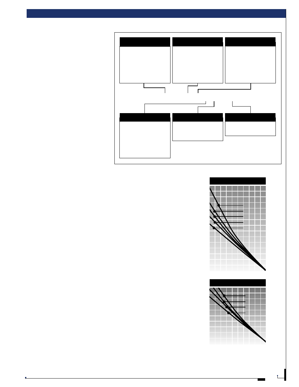
POWER SOURCE RATINGS
1.
4.
Output Voltage Options
1 130/260 VAC Shipped 130VAC
2 260/130 VAC Shipped 260VAC
3 65/130 VAC Shipped 65VAC
4 130/260 VAC Relay Ranging
5 65/130 VAC Relay Ranging
6 65/130/260 VAC Relay Ranging
7 35 VAC Fixed Single Range
8 65/260 VAC Relay Ranging
T Test (Output Monitoring)
D Disconnect
S Synchronization
P Parallel Output Capability
114 150/300 VAC Ouput
116 45-10000 Hz Freq. Range
XXX Consult Factory
5.
Other Standard Options
6.
Non-Standard Options
1001 SL-1 1 TD-116
3.
Input Power Options
-0 208 VAC 3 Phase 47-63Hz
(2253 only)
-1 115 VAC 1 Phase 47-63 Hz
-2 230 VAC 1 Phase 47-63 Hz
-3 208 VAC 1 Phase 47-63 Hz
(not available on 351, 501)
-4 115 VAC 1 Phase 400 Hz
351
501
751
1001
1751
1203
2253
350 VA
500 VA
750 VA
1000 VA
1750 VA
1200 VA
2250 VA
1 Phase
1 Phase
1 Phase
1 Phase
1 Phase
3 Phase
3 Phase
Model
Series
Total
Power
Output
Phases
2.
Model Type
SL Standard Model
SX Peak Load Version
(501, 1001, 1751 Only)
SLE CE mark
SXE CE mark
B S E R I E S
PERCENT OF RATED OUTPUT VOLTAGE
unity pf
0.7 pf
0.5 pf
0.3 pf
PE
R
C
E
NT
OF
R
A
TE
D
OUTPUT
V
OL
T
-AM
P
S
100 90 80 70 60 50 40 30 20 10 0
100
90
80
70
60
50
40
30
20
10
S L / S X S E R I E S
150
140
130
120
110
100
90
80
70
60
50
40
30
20
10
PERCENT OF RATED OUTPUT VOLTAGE
unity pf
0.7 pf
0.5 pf
0.3 pf
0 pf
PE
R
C
E
NT
OF
R
A
TE
D
OUTPUT
V
OL
T
-AM
P
S
100 90 80 70 60 50 40 30 20 10 0
MODEL NUMBER DESCRIPTION