Atec Chroma-63200 Series User Manual
Page 4
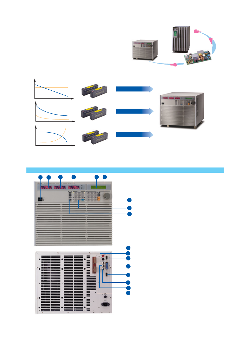
2. ELECTRONIC & ELECTRICAL DEVICES TESTING
Almost all modern electronic and electrical devices are built in with
power supply. Therefore, DC electronic load is an important instru-
ment for these devices during R/D and Q/A phases. For example,
A/D, D/D and D/A stages are nor mally integrated in a UPS.
Consequently, Chroma 63200 electronic loads are helpful to test the
internal A/D and D/D boards of the UPS.
3. BATTERY TESTING
For most of the electronic and electrical devices, their power consumption patterns are constant power. Therefore, the CP mode in 63200
series electronic loads is ideal to use as a discharge load for battery testing.
4. SYSTEM INTEGRATION
Chroma 63200 series electronic loads provide GPIB, RS-232C and RS-485 PC controllable interfaces. The external waveform simulation and
voltage / current monitoring capability make Chroma 63200 family ideal for automatic system integration.
I
V
I
V
I
V
Discharge by CR mode
Discharge by CC mode
Discharge by CP mode
1. Power Switch
2. LED Display:
Voltage read back.
3. LED Display:
Current/ ohm read back.
4. LED Display:
Power read back.
5. LCD Display:
For setting and editing.
6. Rotary knob:
To adjust the loading and parameter setting.
7. Numeric key:
For data setting.
8. Function key:
To select load mode, control mode, and define the
reading specification.
9. System key:
For system config and data store, recall.
10. Load terminal
11. Voltage sense terminal
12. RS-485 connector
13. GPIB connector
14. RS-232C connector
15. Voltage monitor output:
Analog output which indicates the voltage waveform.
16. Current monitor output:
Analog output which indicates the current waveform.
17. External V reference:
External programming voltage input.
2
12
4
6
7
3
8
5
9
1
13
10
11
14
15
17
16
Model: 63203, 63204
PANEL DESCRIPTION