I/ix series : product specifications – Atec California-Instruments-i-iX_SeriesII User Manual
Page 8
www.ProgrammablePower.com
176
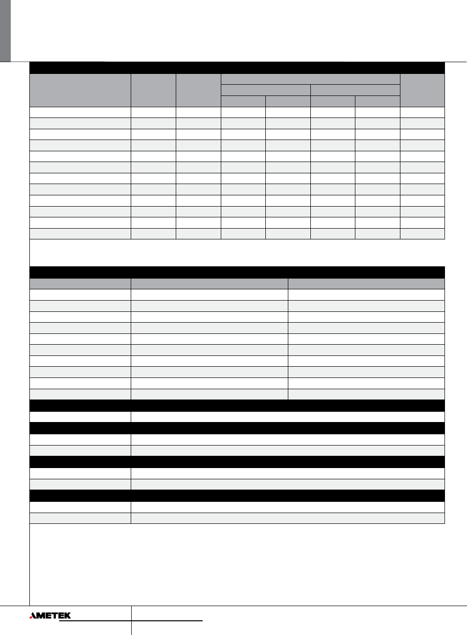
i/iX Series : Product Specifications
Standard controller versions
Model
Output Power AC
Phase Output
Max. current per phase
Input Voltage²
Low V range
High V range
AC
DC
AC
DC
3001i/iX
3 kVA
1
22
15.6
11
7.8
208-240V
5001i/iX
5 kVA
1
37
26
18.5
13
208-240V
5001i/iX-400
5 kVA
1
37
26
18.5
13
400-480V
9003iX1
9 kVA
3
22
15.6
11
7.8
208-240V
10001i/iX¹
10 kVA
1
74
52
37
26
208-240V
10001i/iX-400¹
10 kVA
1
74
52
37
26
400-480V
10002i/iX
3
10 kVA
2
37
26
18.5
13
208-240V
10002i/iX-400
3
10 kVA
2
37
26
18.5
13
400-480V
15001i/iX
1
15 kVA
1
111
78
55.5
39
208-240V
15001i/iX-400
1
15 kVA
1
111
78
55.5
39
400-480V
15003i/iX
1
15 kVA
3
37
26
18.5
13
208-240V
15003i/iX-400
1
15 kVA
3
37
26
18.5
13
400-480V
Note (1): Supplied with System Interface cable(s). Controller in master unit only.
Note (2): All input voltage specifications are for Line to Line three phase except 3001iX and 9003iX which require single phase input only.
Note (3): For 10002iX split phase system specifications, refer to 5001iX for each phase.
Controller
Controller
i
iX
AC mode
X
X
DC mode
X
X
AC+DC mode
X
Transient programming
X
X
Arbitrary waveforms
X
Measurements (standard)
X
X
Harmonic measurements
X
Waveform acquisition
X
Programmable Impedance
X
IEEE / RS232 / USB
X
X
Storage
Non Volatile Mem. storage
16 instrument setups, 200 user defined waveforms
Waveforms
Waveform Types
i Series II: Sine, iX Series II: Sine, Square, Clipped sine, User defined
User defined waveform storage
Four groups of 50 user defined arbitrary waveforms of 1024 points for a total of 200 (One group can be active at a time)
System Interface
Inputs
Remote shutdown, External Sync, Clock/Lock (option)
Outputs
Function Strobe, Clock/Lock (option)
Protection
Over Load
Constant Current or Constant Voltage mode
Over Temperature
Automatic shutdown