Atec Aeroflex-3920 User Manual
Page 21
For the ver y latest specifications visit
w w w.aeroflex.com
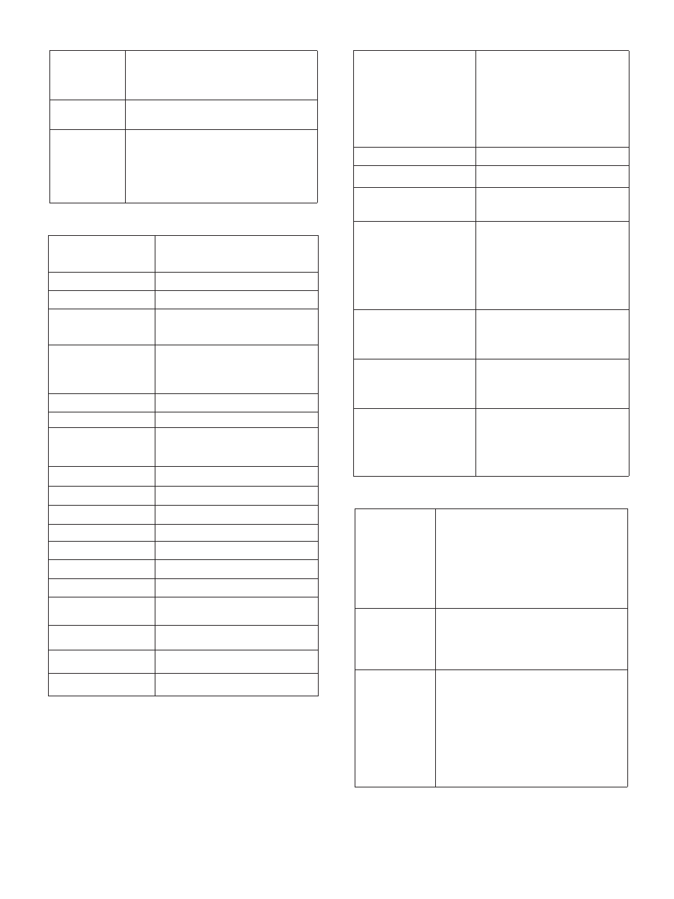
RF RECEIVER
TETRA MEASUREMENTS
GRAPHICAL DISPLAYS
TETRA CHANNEL PLANS AND SIGNALING
Channel Plans
TETRA 380-400 (0 Hz or 12.5 kHz offset)
TETRA 410-430 (0 Hz, -6.25 kHz or
12.5 kHz offset)
TETRA 450-470 (0 Hz or 12.5 kHz offset)
TETRA 805-870 (0 Hz or 12.5 kHz offset)
TETRA 870-921 (0 Hz or 12.5 kHz offset)
No plan and user defined
System Identity
Mobile Country Code, MCC
Mobile Network Code, MNC
Base Color Code, BCC
Location Area Code, LA
Signaling Functions
Mobile parameter control for SSI, GSSI, power
class, receiver class
Registration, test mode registration and
de-registration
Private (individual) call, group call, phone call,
emergency call, user defined call (mobile
terminated)
Call timer and trunking type selection
Cell-re-selection (requires two test sets and a
power splitter)
POWER PROFILE DISPLAY
Display of power versus time for a
complete burst or ramp up/ramp
down intervals measured at the
symbol points and displayed relative
to a TETRA mask (TETRA limits or
user defined) with pass/fail
indication. Measured through a
TETRA filter referenced (0 dB) to
average power.
Dynamic Range
70 dB
Vertical Scale
20 dB/div or 0.1 dB/div in 1, 2, 5
steps
Accuracy
±1.0 dB (±0.6 dB typical) at
symbol points for levels greater
than -10 dB
CONSTELLATION DISPLAY
Polar display of amplitude versus
phase at the symbol point measured
over all symbols (SN0 ~ SN max)
through a TETRA filter. Also available
as a rotated constellation display
where all symbol point
values are mapped to a single
constellation point.
PHASE TRAJECTORY DISPLAY
Polar display of amplitude versus
phase continuously measured over
the duration (SN0 ~ SN max)
through a TETRA filter.
VECTOR ANALYSIS DISPLAYS
Vector error (%), magnitude error
(%) and phase error (degrees)
measured at symbol points (SN0 ~
SN max) through a TETRA filter.
Vertical Scaling
Vector error 0.1%/div to 20%/div in
1, 2, 5 steps
Phase error ±0.1°/div to ±20°/div in
1, 2, 5 steps
Magnitude error ±1.0 %/div to
±20%/div in 1, 2, 5 steps
POWER
Average power across the useful part
of the burst measured at the symbol
points through a TETRA filter
Resolution
0.1 dB
Accuracy
±1.0 dB (±0.6 dB typical)
MODULATION ACCURACY
Modulation accuracy measures the
displacement of symbol points from
their ideal position
Range
20.0% RMS vector error
40.0% Peak vector error
20.0% Residual carrier
Resolution
0.1%
Accuracy
±0.5% at 10% error
BURST TIMING ERROR
Timing error relative to downlink results
available for avg, max, min and worst
case for a sample of up to 250 bursts
Range
±510.00 symbols
Resolution
0.01
Accuracy
±0.05 symbols
Timing offset range
±999.99 symbols
FREQUENCY ERROR
Range
±500.0 Hz
Resolution
0.1 Hz
Accuracy
±15 Hz +frequency standard
accuracy
BER Testing (TETRA MS
T1 mode)
BER, MER and PUEM
BER Testing (TETRA MS
mode)
BER, RBER and MER
BER Testing (TETRA BS
T1 mode)
BER, MER and PUEM
Frequency Range
10 MHz to 1.05 GHz (Standard) (Usable from
100 kHz)
10 MHz to 2.7 GHz (392XOPT058) (Usable
from 100 kHz)
Level Range
T/R Port: -40 dBm to +40 dBm
ANT Port: -80 dBm to 0 dBm
Burst Types
MS: Control Burst (CB), Normal Uplink Burst
(NUB)
BS: Normal Downlink Burst (TS1+2, TS1, and
TS2),
Synchronization Burst, PRBS with no training
sequence
21