Distance-time domain performance summary cont'd, Signal shape examples – Atec Agilent-8703A User Manual
Page 14
Frequency bandwidth (GHz)
Measurement description
0.13 to 12.0
0.13 to 20
Lightwave forward
transmission measurement
Optical-to-optical
51 dBo
51 dBo
Optical-to-electrical
110 dBe
110 dBe
Electrical-to-optical
95 dBe
95 dBe
Lightwave reflection measurement
Optical (Impulse mode only)
44 dBo
44 dBo
Microwave forward
transmission measurement
Electrical-to-electrical
110 dBe
110 dBe
Microwave reflection measurement
Electrical (Impulse mode only)
56 dBe
56 dBe
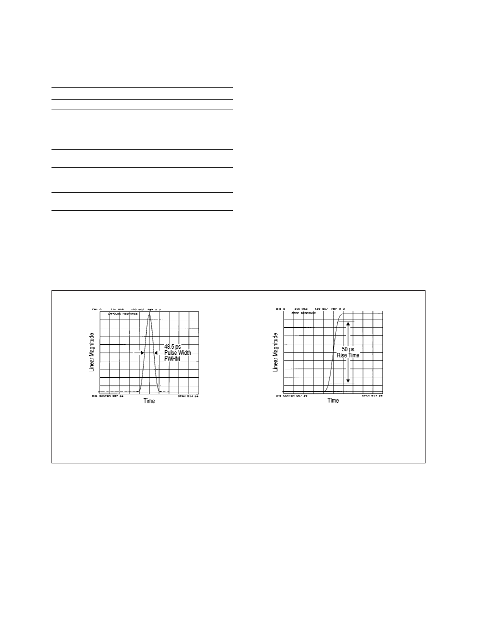
Signal shape examples
The following are graphs of impulse and step signals
generated by the inverse FFT of the 8703A using a 20 GHz
Fspan. Electrical (dBe) and electro-optical (dBe) cases
are not presented since the signal shape is similar to the
lightwave examples shown.
Lightwave
impulse response
transmission test
(DUT = 21 cm single
mode fiber)
Lightwave
step response
transmission test
(DUT = 21 cm single
mode fiber)
45 Limited by maximum lightwave receiver input power, maximum
microwave power and system noise floor. Specified for a 20 GHz
frequency bandwidth, a normal window factor, a 10 Hz IF bandwidth,
a 16 averaging factor and after an appropriate calibration has been
performed (i.e., response & isolation calibration for optical tests,
response & match and isolation calibration for electrical-to-optical and
optical-to-electrical tests, or full 2-port and isolation calibration for
electrical test).
Table 8. Single response
system dynamic range
45
(for distance-time
lowpass impulse and step
response modes, typical).
14
Distance-time domain
performance summary
cont'd